1. REVIT SYSTEMS
For anything that can be drawn sequentially (pipes, ducts, etc.) Revit has a
function to draw them; there are many systems function available in Revit. This
manual will explain how to edit the systems and how to draw them, with an
additional explanation for drawing wires.
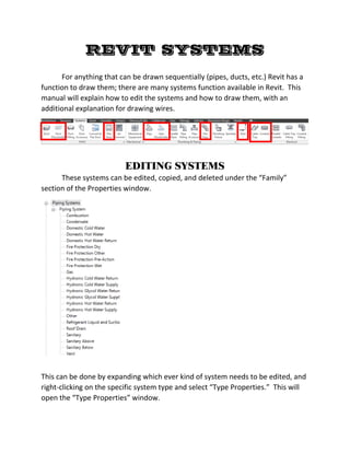
EDITING SYSTEMS
These systems can be edited, copied, and deleted under the “Family”
section of the Properties window.
This can be done by expanding which ever kind of system needs to be edited, and
right-clicking on the specific system type and select “Type Properties.” This will
open the “Type Properties” window.
2. 1) The system and type of system are displayed at the top and can be changed
by clicking the names to show a drop-down list for other options; any of the
types can be duplicated and/or renamed as desired.
2) Anything drawn in Revit can have its lines darkened, color changed, and
given a pattern to distinguish it. Clicking the button next to “Graphic
Overrides” here opens the “Line Graphics” window to edit these features so
that the system will have these features changed from the start and will
apply to the entire project.
This option can be accessed in the project view by right-clicking on the object
and selecting “Override Graphics in View” then select “By Element.”
1
2
3
4
3. 3) The Identity Data section can have information added to it that is specific to
the system type. This can be used later for tagging and visibility purposes.
4) The Rise/Drop section determines what the system will look like at points
where it goes up or down. Clicking on the name will open the “Select
Symbol” window.
When finished editing the system, click OK to apply the settings to the whole
project.
DRAWING PIPE/DUCT SYSTEMS
Clicking on a system function will open the place options for how the
system.
These options can be used as needed to draw the systems as accurate as desired.
Note: Sloped systems can be difficult when trying to connect branches to each
other. Use the “Ignore Slope to Connect” option in these instances.
The size, level, and height of the system can be changed in the Properties window
before drawing them, as well as at the top left of the view window before/while
drawing them.
4. DRAWING WIRES
Wires are a different kind of system; they only appear in plan views, not in
3D views. There are three styles for drawing wires: Arc, Chamfered, and Spline;
these styles can be chosen by clicking the arrow below the “Wire” button. After
selecting the desired wire style, the Properties window will change.
1) By default there are two types of wires based on the type of insulation of
each wire. Clicking “Edit Type” will open the “Type Properties” window to
duplicate and/or rename wire types and edit their parameters.
2) The number of conductors on a wire can be changed in the Properties
window. The conductors will face in the direction of the end of the drawn
wire, so wires must be drawn in the direction of the circuit flow. The
appearance of the conductors can be edited in the Electrical Settings, which
will be covered in a later manual.
1
2