1. Piezoelectric and Piezoresistive Sensors
Introduction
Piezo is derived from the Greek word piezein, “to squeeze.” Piezoelectric materials
produce a voltage when strained. Piezoresistive materials exhibit a change in resistance
when subjected to pressure.
Piezoelectric Effect
When pressure (stress) is applied to a material it creates a strain or deformation in the
material. In a piezoelectric material this strain creates an electrical potential difference, a
voltage. The effect is reversible. When an electric potential is applied across two sides of
a piezoelectric material, it strains. Both effects were discovered by Jacques and Pierre
Curie in 1880-1. The piezoelectric effect is found in materials with a specific electical
crystalline structure. These are known as piezoelectric materials.
Piezoelectric Materials
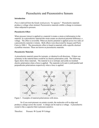
A piezoelectric material cannot be isotropic, or identical in all directions. If there was
symmetry in the material there would be no electric polarization yield. The following
figure shows three materials. The material in a) is isotropic and yields no resultant
electric polarization when a force is applied. The materials in b) and c) yield parallel and
perpendicular polarizations respectively when a force is applied.
Figure 1. Examples of material polarizations with stress.
So if you exert pressure on certain crystals, the molecules will re-align and
produce a charge across the crystal. A charge can be read as a voltage. A piezoelectric
crystal is like a capacitor that is pressure-sensitive.
Therefore:
Pressure à Crystal à Voltage
2. Of the natural piezoelectric materials, the most frequently used are quartz and
tourmaline. Of the synthetic materials, those that have been more extensively used are
not crystalline but ceramics. These are formed by many little tightly compacted
monocrystals (about 1 micrometer in size). These ceramics are ferroelectrics, and to
align the monocrystals in the same direction (i.e. to polarize them), they are subjected to a
strong electric field during their fabrication process. The applied field depends on the
material thickness, but values of about 10 kV/cm are common at temperatures slightly
above the Curie temperature (at higher temperatures they are too conductive). The Curie
temperature or Curie point is when the material heats up hot enough so that its properties
turn from ferromagnetic to paramagnetic. In other words, if a crystal is heated up above a
certain temperature, the polarities of the monocrystals will return to random directions
instead of all being organized in one direction. This creates a limiting factor of
temperature for piezoelectric materials.
Piezoelectric ceramics display a high thermal and physical stability and can be
manufactured in many different shapes and with a broad range of values for the
properties of interest (dielectric constant, piezoelectric coefficient, Curie temperature,
etc.). Their main shortcomings are the temperature sensitivity of their parameters and
their susceptibility to aging (loss of piezoelectric properties) when they are close to their
Curie temperature. The most commonly used ceramics are lead zirconate titanate, barium
titanate, and lead niobate. Polymers are also used as piezoelectric materials. A polymer
lacking symmetry known as polyvinylidene fluoride is common because it can be made
into shapes that are impossible for solid materials.
Equations
The generated voltage from a piezoelectric material can be calculated from the following
equation.
V = Sv * P * D
Where V = Piezoelectric generated voltage (Volts)
Sv = Voltage sensitivity of the material (Volt *meters / Newton)
P = Pressure (N/m2)
D = thickness of material (meters)
Voltage sensitivity values are provided with the material when received from the
manufacturer. Different materials and different geometry cuts give different sensitivities.
Applications
•
•
•
•
Ultrasonic transmitters and receivers.
Frequency references.
Temperature sensors (resonant frequency changes with temperature)
Accelerometers (used with a seismic mass) (See discussion in section 5-3.3 in
Carstens text). See notes on accelerometer calibration in 9.7 and 9.8 DRM
3. • Microphones and loudspeakers (small loudspeakers with poor audio characteristics =
beepers)
• Pressure sensor
• Force sensor
Advantages
•
•
•
•
•
•
•
•
Low cost
High sensitivity
High mechanical stiffness
Broad frequency range
Exceptional linearity
Excellent repeatability
Unidirectional sensitivity
Small size
Limitations
The crystal gives off a voltage but it is not a battery. There is very little energy available.
Analogy: Could you move a car with 200 000 psi pressure?
Point of a needle 0.01” x 0.01” and push with 20 lbs = 200 000 psi à high pressure but
low force
The impedance of the crystal is very high. Therefore we need to measure the
voltage with a higher impedance device to avoid draining the tiny store of energy that is
there. The typical resistance and capacitance values of an 8 mm crystal are about 1015 Ω
and 10-15 Farads. These are extremely high impedances. This means that when we
amplify the signal we must consider the capacitance of the lead wires and the input
impedance of the amplifier. Normally in instrumentation design we ignore these factors
because sensors generally have impedances in the range of 103 Ω rather than 1015 Ω . In
practice this means that we have a limited amount of time available to take a fixed
measurement before the charge drains away. If the measurement changes rapidly then
there is much less of a problem. IE the sensor has a very poor DC response but good AC
response.
Piezoelectric sensors also react to temperature as well as pressure. They must be
operated in their design range to maintain accuracy. Out of their design range they react
so strongly to temperature that they can be used as temperature sensors. The following
figure illustrates this. As can be seen if the crystal is operated around 20°C then the
temperature can vary a few degrees with minimal effect on the frequency. In this range
we could use the crystal as a frequency reference. Around 50°C the response to
temperature is strong and somewhat linear. In this operating range we could use the
crystal as a temperature sensor. The sensitivity is a function of temperature.
4. Figure 2. A graph of frequency change vs. temperature for a piezoelectric crystal.
The response of piezoelectric sensors drifts with temperature and if the
temperature is too high (above the Curie point) the device no longer works. For example
the Curie temperature for Quartz is about 550° for Barium titanate it is about 125°
C;
C.
Piezoelectric sensors work to very high frequencies, up to 100 KHz. This makes
them suitable for ultrasonic sensors (receivers) and actuators (transmitters). The
frequency response is a function of the size and cut of the crystal. Very small crystals
respond into the MHz range and respond very strongly at a particular resonant frequency.
In this mode they are the primary timing devices of computers, watches and most other
modern electronic timing applications.
The characteristics of the crystal drift with age. It takes days to weeks for a
crystal to settle after it is cut and the characteristics can change during this time. Crystals
age much more rapidly near their Curie point.
5. Figure 3. This diagram shows that the output of the crystal drifts steadily for months and
then tapers off to a steady value. Note the scale of the Y axis (ppm)
Piezoresistive sensors
As their name implies, piezoresistive sensors change resistance when pressure is applied.
The development of piezoresistive materials was an outgrowth of semiconductor research
conducted by Bell Telephone Laboratories in the early 1950’ This research eventually
s.
led to the transistor. Piezoresistive sensors are made from semiconductor materialsusually silicon, with boron as the trace impurity for the P-type material and arsenic as the
trace impurity for N-type material.
In general, materials exhibit a change in resistivity with strain. For a
semiconductor, this change in resistivity with strain can be very large. Resistivity is a
direct measure of the charge carrier density.
The resistivity of a semiconductor material=
1 / [(electron charge)*(# of charge carriers)*(mobility of charge carriers)]
The effect of applied stress is to change the number and the mobility of the charge
carriers within a material, thus causing large changes in resistivity. This resultant change
in resistivity is called the piezoresistive effect. The electron charge and the # of charge
carriers can be controlled during the manufacturing process by changing the amount and
type of trace impurity added to the material. By controlling the manufacturing process,
the material’ characteristics can be easily reproduced.
s
Piezoresistive sensors can be manufactured in similar processes to electronic
integrated circuits and can be made extremely small with micromachining. They have
been used in medical research to implant into tissue to measure bodily stresses (bed-sore
6. studies) and can be made small enough that they can be inserted into the brain with
minimal cell damage. They can also be used to make strain gauges (gages?) that can
measure stresses of µN. They have also been used to build micromachined
accelerometers.
Compared to piezoelectric materials, piezoresistive materials have very high
sensitivity and better low frequency response.
Strain Gages
Conceptually a strain gage is simple a resistive element that is stretched when strained.
When the material is stretched it becomes longer (resistance increases) and the diameter
degreases (resistance increases again). It is theoretically possible to build a strain gage of
this type but practical problems arise; primarily the resistance changes are very small and
hard to measure and the gage becomes large and unwieldy. In order to magnify the strain
effect the gage is usually laid out in a concertina pattern. This gage clearly is most
sensitive in the direction of longitudinal stretching.
Direction of maximum
sensitivity
Electrical resistance strain gages are thin metal-foil grids that can be adhesively bonded
to a surface. When the surface is stressed, strain develops and is transmitted to the foil
grid. The resistance of the foil grid changes in proportion to the load induced strain. A
key problem in using strain gages is making sure the gage is firmly bonded to the surface
so that the microscopic strains occurring in the material are faithfully transmitted into the
strain gage. This type of strain gage is not a piezoresistive sensor, as the material is not a
semiconductor and the pressure does not directly affect the resistivity.
A strain gage exhibits a percent change in resistance that is directly proportional
to the strain applied.
Strain = dL/L
dR/R=Sg*Strain
Gage factor= Sg is the coefficient to convert strain to dR/R
The gage factor for most metals is generally about 2. Standard values of resistance for
strain gages are 350 ohms and 120 ohms.
The strain gage is generally used in conjunction with a Wheatstone bridge to
make a strain transducer. The maximum current rating of a strain gage is 25 mA. (250
mW for semiconductors).
7. Types
Made from all kinds of different metals and alloys such as constantan, advance, karma,
nichrome, and germanium.
Since strain gages are very directional in their sensing. It is common to use a pattern of
strain gages with several gages on a single piece of foil oriented in different directions.
The gage is bonded to the surface of the material prior to the connection leads being
attached. It is common to use a separate strain relief pad near to the gage. The connection
is first made from the gage to the strain relief pad with very light gage wire and then
between the strain relief pad and the transducer cable.
Applications
Strain gages are often used in mechanical engineering and related disciplines. The
expected strain in the material is calculated and then a suitable gage is selected and
bonded on to the surface.
Strain gages are also often build into load cells. A load cell is a mechanical support for a
system or structure with strain gages bonded to its internal surface. It measures the strain
and thus the force applied to the structure. This is commonly used to measure weight. For
example a weighbridge for trucks could be supported on load cells or a tank of fluid
could be supported on load cells. When used in this manner care must be taken to ensure
the load passes through the load cells and not through any other support structure and the
load must pass vertically through the cell. IE we must balance the load on the cells and
the cells will typically have rounded tops so that no side loads can be passed through.
Because load cells are built with strain gages, care must be taken not to break the bond
between the gage and strained surface. For this reason load cells and other strain gage
applications cannot tolerate shock loading or severe overloading. Load cells are typically
8. rated for an absolute maximum of 150% of nominal load. IE if you apply more than 150
Kgs to a 100 Kg load cell you are likely to destroy it.
Here are some other typical applications.
•
•
•
•
•
•
Tactile sensors in robots
Measure torsion
Measuring stress
Measuring strain
Measuring pressure
Measuring force
Advantages
•
•
•
•
•
•
•
•
•
•
•
Bond excellently to most surfaces
Readily dissipates heat
Minimal sensitivity to transverse strain (perpendicular to intended direction)
Small size
High frequency response
Rugged
High linearity
Low impedance
Good spatial resolution (measure strain at a point)
Generally unaffected by ambient conditions
Can be wrapped around curved surfaces unlike the piezoresistor.
Disadvantages
• Resistance changes with temperature
• Strain gage grid expands and contracts at a different rate than the surface it is attached
to
• Gage factor changes with temperature as well
• Compared to piezoresistive sensors strain gages have much lower sensitivity (typical
gage factor 2 vs. 100 for the piezoresistive sensor).
Sources: The majority of the information for this handout was taken from:
Carstens, Electrical Sensors and Transducers, Prentice Hall, 1993, pages 185-199
Dally, Riley, and McConnell, Instrumentation for Engineering Measurements, Wiley,
1993, 2nd Ed, pages 124-126
Figliola, Theory and Design for Mechanical Measurements, Wiley, 1995, 2nd Ed., pages
485-519
9. Pallas-Areny, Sensors and Signal Conditioning, Wiley, 1991, pages 45-51 and 247-57
Nachtigal, Instrumentation and Control, Wiley, 1990, pages 102, 311-2, 379-88
Problems
1. What voltage is generated from a crystal 8 mm thick if 2MPa (2x10⁶ N/m2) of
pressure is applied and the crystal is
a.
X-cut longitudinal quartz Sv = 0.055 V*m/N
b.
Barium titanate
Sv = 0.011 V*m/N
2. A 350 ohm strain gage with a gage factor of 2 is subjected to a strain of 0.001 in/in.
What is the resulting change in resistance?
3. Which device has a higher gage factor, a semiconductor strain gage or a foil grid
strain gage?