1. Fact sheet
Construction of high bridges through Sugarloaf Range
The eastern section of the Hunter Expressway travels through steep terrain in the Sugarloaf Range.
The project team is building three high bridges, known as viaducts, to carry the new expressway
through the range. This fact sheet outlines the challenges of building in Sugarloaf Range and the
environmental benefits of the viaducts.
AUGUST 2012 hunter expressway
The route of the Hunter Expressway crosses the Sugarloaf
Range to the west of the F3 Freeway and involves
crossings of a number of deep valleys. At three of these
sites large bridge structures called viaducts are being used
to carry the expressway over the valleys.
The viaducts have lengths of approximately 330 metres,
255 metres and 200 metres and span lengths of up to 75
metres. There are twin viaducts at each site making a total
of six structures. The viaducts have concrete box girder
superstructures supported on hollow concrete piers. The
decks are 11.5 metres between kerbs. The depth of the box
girders varies from 3 metres to 4.2 metres, which provides
for two lanes of traffic in each direction and shoulders.
The height of the decks above ground at the piers varies
from 34 metres to 42 metres.
To minimise the amount of on-site construction the piers
and decks are being constructed using precast concrete
elements, known as segments. This reduces the risks
of working at heights and of damaging the environment
through spills and additional clearing. The time for
construction on site is also greatly reduced.
Erection of the columns is done from the ground using
large cranes to lift the segments into place. Tensioned steel
strands are then used to hold the segments together and
carry the loads from the superstructure.
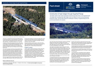
The deck segments are assembled using a specially designed
steel launching truss which sits on top of the piers and carries
the segments from the transporter to their final location.
The launching truss contains approximately 1000 tonnes of
steel when fully assembled and is 165 metres in length and
16 metres high.
The superstructure is assembled using the ‘balanced
cantilever’ method by placing segments alternately on
either side of the pier until the superstructure reaches
the mid-spans. Tensioned steel strands are used to hold
the segments together and carry the loads from the
superstructure and traffic.
The precast concrete segments are being produced in
a casting yard adjacent to the main project office near
Buchanan. This yard has been set up specifically for the
project, together with a concrete batch plant to supply
concrete for the bridgeworks.
There are 177 segments for the piers and 566 segments
for the superstructures. During production two moulds are
used for the column segments and three moulds for the
deck segments. The segments weigh up to 110 tonnes.
Transport of these large segments from the casting yard
to the bridges involves specialised transporters. The route
of the transport includes parts of George Booth Drive
between Seahampton and Buchanan. The alliance has
built access roads to get to the bridge sites from George
Booth Drive.
The column segments travel along George Booth Drive
from the project office entrance to Seahampton and use
Seahampton Road to access the bridge sites. Traffic
will experience some short delays while the transporters
enter and exit George Booth Drive. Due to the narrow
width of George Booth Drive between Tasman Mine and
Seahampton traffic will need to be stopped for short
periods while the segment transporter moves through.
The deck segments travel along George Booth Drive from
the project office entrance to Blue Gum Creek and use
the site access adjacent to access the bridge sites. Due to
the larger size and weight of the deck segments and the
need to move them at a relatively slow speed, traffic will
experience some short delays.
During the erection of each column or deck span there
will be several segment movements per day, over several
days. Movement of the precast segments started in
September 2011 and will continue until late 2012.
Project Funding
The $1.7 billion Hunter Expressway is jointly funded with
the Australian Government providing $1.5 billion and
the NSW Government providing up to $200 million. It is
scheduled to open to traffic at the end of 2013, weather
permitting. The new four-lane expressway is being
constructed under two contracts, with the eastern section
(F3 Freeway to Kurri Kurri) being built by the Hunter
Expressway Alliance. The Alliance includes Roads and
Maritime Services (RMS), Thiess, Hyder Consulting and
Parsons Brinckerhoff (Australia).
Roads and Maritime Services
Locked Bag 30, Newcastle, NSW 2300 | T 1800 001 267 (toll free) | E hunter.expressway@rms.nsw.gov.au
www.rms.nsw.gov.au/hex
A large, steel launching truss is being used to build the high bridges through Sugarloaf Range.
Construction of the bridge deck of viaduct three in Sugarloaf Range.
Construction of high bridges through Sugarloaf Range
2. Construction of high bridges through Sugarloaf Range
Erecting deck segments for the eastbound carriageway for viaduct three over Blue Gum Creek.
Launching gantry with deck segment on the first pier.
Pre-cast yard for bridge segments at the Hunter Expressway Alliance site compound at Buchanan.
The launch truss on the high vertical pier at viaduct three. Segment erection in progress.