Workshop - Best of Both Worlds_ Combine KG and Vector search for enhanced R...
Chemical bonding part 2
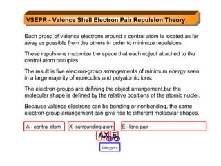
1. VSEPR - Valence Shell Electron Pair Repulsion Theory Each group of valence electrons around a central atom is located as far away as possible from the others in order to minimize repulsions. These repulsions maximize the space that each object attached to the central atom occupies. The result is five electron-group arrangements of minimum energy seen in a large majority of molecules and polyatomic ions. The electron-groups are defining the object arrangement,but the molecular shape is defined by the relative positions of the atomic nuclei. Because valence electrons can be bonding or nonbonding, the same electron-group arrangement can give rise to different molecular shapes. AX m E n A - central atom X -surrounding atom E –lone pair integers
2. Factors Affecting Actual Bond Angles Bond angles are consistent with theoretical angles when the atoms attached to the central atom are the same and when all electrons are bonding electrons of the same order. ideal 120 0 120 0 larger EN greater electron density Lone pairs repel bonding pairs more strongly than bonding pairs repel each other. 95 0 122 0 116 0 real Effect of Double Bonds Effect of Nonbonding(Lone) Pairs
3.
4. Figure 10.2 the five basic molecular shapes linear trigonal planar tetrahedral trigonal bipyramidal octahedral
5. Figure 10.3 The single molecular shape of the linear electron-group arrangement. Examples: CS 2 , HCN, BeF 2
6. Figure 10.4 The two molecular shapes of the trigonal planar electron-group arrangement. Examples: SO 3 , BF 3 , NO 3 - , CO 3 2- Examples: SO 2 , O 3 , PbCl 2 , SnBr 2 Class Shape
7. Figure 10.5 The three molecular shapes of the tetrahedral electron-group arrangement. Examples: CH 4 , SiCl 4 , SO 4 2- , ClO 4 - NH 3 PF 3 ClO 3 H 3 O + H 2 O OF 2 SCl 2
9. Figure 10.7 The four molecular shapes of the trigonal bipyramidal electron-group arrangement. SF 4 XeO 2 F 2 I F 4 + I O 2 F 2 - ClF 3 BrF 3 XeF 2 I 3 - I F 2 - PF 5 AsF 5 SOF 4
10. Figure 10.8 The three molecular shapes of the octahedral electron-group arrangement. SF 6 I OF 5 BrF 5 TeF 5 - XeOF 4 XeF 4 I Cl 4 -
11. Figure 10.9 A summary of common molecular shapes with two to six electron groups.
12. Figure 10.10 The steps in determining a molecular shape. Molecular formula Lewis structure Electron domain geometry Bond angles Molecular shape (AX m E n ) Electron domain geometry =No. of atoms attached + no. of lone pairs 2- linear 3- trigonalpyramidal 4- tetrahedral 5- trigonal bipyramidal 6- octahedral Step 1 Step 2 Step 3 Step 4
13. SAMPLE PROBLEM 10.6 Predicting Molecular Shapes with Two, Three, or Four Electron Groups Electron domain geometry : tetrahedral bond angle: 109.5 0 Molecular geometry: trigonal pyramidal . The type of shape is AX 3 E PROBLEM: Draw the molecular shape and predict the bond angles (relative to the ideal bond angles) of (a) PF 3 and (b) COCl 2 . SOLUTION: (a) For PF 3 - there are 26 valence electrons, 1 nonbonding pair
14. SAMPLE PROBLEM 10.6 Predicting Molecular Shapes with Two, Three, or Four Electron Groups continued (b) For COCl 2 , C has the lowest EN and will be the center atom. There are 24 valence e - , 3 atoms attached to the center atom. Electron domain geometry: trigonal planar Type : AX 3 Molecular geometry: trigonal planar bond angle= 120 0 124.5 0 111 0
15.
16. (b) BrF 5 - 42 valence e - ; 5 bonding pairs and 1 nonbonding pair on central atom. Electron domain geometry : octahedral Molecular geometry shape is AX 5 E, square pyramidal. Bond angles : 90
17. Figure 10.12 The orientation of polar molecules in an electric field. Electric field OFF Electric field ON
18.
19. SAMPLE PROBLEM 10.9 Predicting the Polarity of Molecules (a) Ammonia, NH 3 (b) Boron trifluoride, BF 3 (c) Carbonyl sulfide, COS (atom sequence SCO) bond dipoles molecular dipole The dipoles reinforce each other, so the overall molecule is definitely polar . PROBLEM: predict whether each of the following molecules is polar and show the direction of bond dipoles and the overall molecular dipole when applicable: PLAN: Draw the shape, and combine the concepts to determine the polarity. SOLUTION: (a) NH 3
20. SAMPLE PROBLEM 10.10 Predicting the Polarity of Molecules continued (b) BF 3 has 24 valence e - and all electrons around the B will be involved in bonds. The shape is AX 3 , trigonal planar. F (EN 4.0) is more electronegative than B (EN 2.0) and all of the dipoles will be directed from B to F. Because all are at the same angle and of the same magnitude, the molecule is nonpolar. 120 0 (c) COS is linear. C and S have the same EN (2.0) but Oxygen is more electronegative and the molecule is quite polar(DEN) so the molecule is polar overall.
21. SAMPLE PROBLEM Combined Concepts Electron domain geometry : trigonal planar Molecular geometry : AX 2 E - bent Bond angles : 120 Lewis Structure Formal charge of the central atom: -1 Hybridization of the central atom: sp 2 Polarity : polar PROBLEM: (a) SnCl 2 SOLUTION: 18 valence e - ;
22. SAMPLE PROBLEM Combined Concepts Electron domain geometry : linear Molecular geometry : AX 2 - linear Bond angles : 180 Lewis Structure Formal charge of the C: 0 Hybridization of the C: sp Polarity : nonpolar PROBLEM: (b) C 2 H 2 SOLUTION: 10 valence e - ; all electrons around central atom will be in bonding pairs;
23. The Central Themes of MO Theory A molecule is viewed on a quantum mechanical level as a collection of nuclei surrounded by delocalized molecular orbitals . Atomic wave functions are summed to obtain molecular wave functions. If wave functions reinforce each other, a bonding MO is formed (region of high electron density exists between the nuclei). If wave functions cancel each other, an antibonding MO is formed (a node of zero electron density occurs between the nuclei).
24. Properties of Molecular orbitals *holds maximum of 2 electrons of opposite spins *have definite/discrete energy states *electron density distribution can be represented by contour diagrams (similar to AO’s – s, p, d, f) *MO is associated with the entire molecule *MO’s are formed by the linear combination of atomic orbitals (AO’s) and the overlap results in the formation of sigma ( ) and pi ( ) bonds
25. Figure 11.14 Contours and energies of the bonding and antibonding molecular orbitals (MOs) in H 2 . The bonding MO is lower in energy and the antibonding MO is higher in energy than the AOs that combined to form them.
26. Bond Order = ½ (bonding electrons – nonbonding electrons)
27. Figure 11.15 The MO diagram for H 2 . Energy MO of H 2 * 1s 1s H 2 bond order = 1/2 (2-0) = 1 Filling molecular orbitals with electrons follows the same concept as filling atomic orbitals. AO of H 1s AO of H 1s
28. Figure 11.16 MO diagram for He 2 + and He 2 . Energy MO of He + * 1s 1s MO of He 2 He 2 + bond order = 1/2 He 2 bond order = 0 AO of He + 1s AO of He 1s AO of He 1s * 1s 1s Energy AO of He 1s
29. SAMPLE PROBLEM 11.3 Predicting Stability of Species Using MO Diagrams SOLUTION: MO of H 2 + bond order = 1/2(1-0) = 1/2 H 2 + does exist MO of H 2 - bond order = 1/2(2-1) = 1/2 H 2 - does exist configuration is ( 1s ) 2 ( 2s ) 1 PROBLEM: Use MO diagrams to predict whether H 2 + and H 2 - exist. Determine their bond orders and electron configurations. PLAN: Use H 2 as a model and accommodate the number of electrons in bonding and antibonding orbitals. Find the bond order. 1s AO of H 1s AO of H + 1s 1s AO of H AO of H - configuration is ( 1s ) 1
30. Figure 11.18 Li 2 bond order = 1 Be 2 bond order = 0 Bonding in s-block homonuclear diatomic molecules. Energy Li 2 Be 2 * 2s 2s 2s 2s 2s 2s * 2s 2s
31. Figure 11.19 Contours and energies of s and p MOs through combinations of 2p atomic orbitals.
32. Figure 11.20 Relative MO energy levels for Period 2 homonuclear diatomic molecules. MO energy levels for O 2 , F 2 , and Ne 2 MO energy levels for B 2 , C 2 , and N 2 without 2s-2p mixing with 2s-2p mixing
33. Figure 11.21 MO occupancy and molecular properties for B 2 through Ne 2
34. SAMPLE PROBLEM 11.4 Using MO Theory to Explain Bond Properties SOLUTION: Explain these facts with diagrams that show the sequence and occupancy of MOs. N 2 has 10 valence electrons, so N 2 + has 9. O 2 has 12 valence electrons, so O 2 + has 11. PROBLEM: As the following data show, removing an electron from N 2 forms an ion with a weaker, longer bond than in the parent molecules, whereas the ion formed from O 2 has a stronger, shorter bond: PLAN: Find the number of valence electrons for each species, draw the MO diagrams, calculate bond orders, and then compare the results. Bond energy (kJ/mol) Bond length (pm) N 2 N 2 + O 2 O 2 + 945 110 498 841 623 112 121 112
35. SAMPLE PROBLEM 11.4 Using MO Theory to Explain Bond Properties continued 2s 2s 2p 2p 2p 2p N 2 N 2 + O 2 O 2 + bond orders 1/2(8-2)=3 1/2(7-2)=2.5 1/2(8-4)=2 1/2(8-3)=2.5 bonding e - lost antibonding e - lost 2s 2s 2p 2p 2p 2p
36. Energy MO of HF Figure 11.23 The MO diagram for HF AO of H 1s 2p x 2p y AO of F 2p
37. Energy Figure 11.24 The MO diagram for NO MO of NO possible Lewis structures 2s AO of N 2p * 1s 1s 2s AO of O 2p 2p 2p * 2p * 2s
38.
39. a. O 2 2- 1. Molecular orbital diagram: 2s 2 * 2s 2 2p 4 2p 2 * 2p 4 2.Electronic configuration using MO: 3.Bond order = ½(8-6) = 1
40. b. N 2 1. Molecular orbital diagram: 2s 2 * 2s 2 2p 4 2p 2 2.Electronic configuration using MO: 3.Bond order = ½(8-2) = 3
42. Figure 10.1 The steps in converting a molecular formula into a Lewis structure. Molecular formula Atom placement Sum of valence e - Remaining valence e - Lewis structure Place atom with lowest EN in center Add A-group numbers Draw single bonds. Subtract 2e - for each bond. Give each atom 8e - (2e - for H) Step 1 Step 2 Step 3 Step 4
43. Figure 10.12 The steps in determining a molecular shape. Molecular formula Lewis structure Electron-group arrangement Bond angles Molecular shape (AX m E n ) Count all e - groups around central atom (A) Note lone pairs and double bonds Count bonding and nonbonding e - groups separately. Step 1 Step 2 Step 3 Step 4 See Figure 10.1
45. Metallic Bond – bonding in which bonding electrons are relatively free to move throughout the three-dimensional structure. Physical Properties of Metals *Metal surfaces has a characteristic luster *Metals have high electrical conductivity *Metals have high thermal/heat conductivity *Most metals are malleable and ductile
46. Electron Sea Model for Metallic Bonding *in this model, the metal is pictured as an array of metal cations in a “sea” of electrons. *electrons are confined to the metal by electrostatic attractions to the cations, and they are uniformly distributed throughout the structure. *above physical properties of metal can be explained by this model
47. Molecular-Orbital Model for Metals or Band Theory *in a metal the number of atomic orbitals that interact or overlap is very large thus, the number of molecular orbitals is also very large. *it has an energy band – numerous and continuous tiny energy separation of between metal orbitals. *electrons available for metallic bonding do not completely fill the available molecular orbitals. It is partially filled. *electrons at the top require a little input to be promoted to still higher energy orbitals.
48. Metallic conductors have partially filled energy bands, as shown in (a). Insulators have filled and empty energy bands, as in (b). Notes: According to the MO theory metals are able to conduct electricity because there are more molecular orbitals in the band than are necessary to accommodate the bonding electrons. In metals an excited electron may easily move to a nearby higher orbital. The bonding and antibonding molecular orbitals of insulators such as diamond are separated by a large energy gap so there are no nearby orbitals for the electrons to move to, making diamond a poor conductor of electricity.