NFCRFID Ripe for Application Expansion_ElectronicDesign
Implementing the CAN Protocol in 3G Equipment Designs
1. News & Analysis
Implementing the CAN Protocol in 3G Equipment
Designs
Implementing the CAN Protocol in 3G Equipment Designs
Hamed M. Sanogo, Motorola
12/23/2002 10:08 AM EST
Post a comment
NO RATINGS
LOGIN TO RATE
inShare7
The controller area network (CAN) communication protocol, initially developed for the
automotive industry as the prime choice of all new automotive applications is becoming
increasingly popular technology for the wireless industry. The protocol's error management,
fault isolation, and fault tolerance capabilities provide some nice benefits to design engineers
building base transceiver station (BTS) and mobile switching center (MSC) equipment for
emerging third-generation wireless networks.
In this article, we'll provide an overview of the CAN protocol and its impact on the
development of cellular equipment. The article will also examine some changes that will
make CAN even more useful in wireless designs.
Opening the CAN
CAN, a serial communication network, was originally designed and developed by Robert
Bosch GmbH in the late 1980s for the automotive industry for an in-vehicle networking. CAN
is for embedded distributed systems what LAN/WAN is for computing.
CAN is the network for microprocessor based systems. It is an ISO 11898 standard
communication protocol, which covers layers 1 (physical) and 2 (data link) of the OSI model.
For the physical layer, a twisted pair multi-drop cable is specified with a length ranging from
1000 meters at to bit rate of 40 kbit/s to 40 meters at the bit rate of 1 Mbit/s. It is a half-
duplex network system suited for "high-speed" applications using short messages.
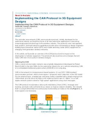
The CAN protocol incorporates a data cyclic redundancy check (CRC), message error
tracking, and fault node confinements as means to improve network reliability. The network
itself is a single differential line continuously monitored by all nodes on the link(Figure 1). A
clock signal is not necessary.
Click here for Figure 1
2. Figure 1: Diagram of the CAN bus network.
The media access control (MAC) layer is based on a carrier sense multiple access with
collision detection and resolution (CSMA-CD/CR/CA) scheme. Message arbitration is
accomplished 1 bit at the time. As each node transmits a bit, it checks to see if the bus is the
same state that it transmitted. If it is, it continues. If not, then another node has transmitted a
dominant bit. The first node then knows that it has lost arbitration and stops message
transmitting soon after. This makes it similar in some respects to the Ethernet protocol,
except that the "CAN-sending-node" does not have to stop message transmission when the
network detects a collision.
The messaging principle of the CAN communication protocol is short data messages—8
bytes maximum—. This principle is transmitted from any node on the bus using a multicast
technique(Figure 2). The message is not intended to any specific node; however, each
transaction's content is labeled by an identifier, which is unique across the network. This
unique identifier also determines the priority of the messages it has labeled.1
Click here for Figure 2
Figure 2: Diagram of the CAN data frame.
The Fault Tolerance Advantage
There is no doubt that the telecom industry's (or any other industry which has decided to use
CAN) most poignant reason to use CAN is the protocol's reliable error detection as well as
signaling and fault confinement mechanism.
Historically, BTS designs have employed differential bus technologies (RS485, RS422,
LVDS, and others). However, the implementation of these buses in a wireless architecture is
a questionable choice. Designers have implemented these differential buses in a point-to-
point configuration network architecture even though many can be implemented in a multi-
drop architecture configuration fashion. Since some of these protocols offer a multi-drop
capability, designers may create a design that can cause a whole network of nodes to go
down if a fault occurs on a single node. With operators demanding five nines (99.999%)
reliability, the potential for multi-drop operation is forcing designers to evaluate other bus
options.
Under the CAN approach, embedded nodes remove themselves from the network when an
error or fault occurs. By doing this, the CAN network prevents the potential collapsing
situation by a single node as described above. Thus, by using the CAN protocol, wireless
designers can create an embedded network between all the field replacement cards (PCBs)
that can operate even in the light of error conditions. This network can be managed by a
controller card (the card playing the role of master) that directly communicates with any card
within the BTS via short messages.
The CAN protocol implements five different error types. These are bit, stuff, CRC,
3. acknowledgement, and form errors. Whenever any node on the network detects any of these
errors, that node immediately aborts transmission by sending an Error Flag, 6 consecutives
dominant bit, at the next bit time.
To facilitate fault confinement, CAN also implements two types of error counters; transmit
error counter (TEC) and receive error counter (REC). When an error occurs, the sending
node increment its TEC by 8 while the receiving node increment their REC by 1. When the
TEC reaches above 255, the node goes on the "Bus Off" state. The weighing factor is clearly
higher for the transmit node because it is desired that the node sending bad messages on
the network be the one removed. A bus-off node is not allowed to have any influence on the
bus (e.g., output drivers switched off). This feature of the CAN protocol has made it attractive
for cellular infrastructure designers to whom the fear to use a multi-drop network thing of the
past.
In addition, different PHY layer implementations of CAN exist where the network is made to
work in certain fault condition such as bus short to ground, bus short the Vcc, as well as CAN
differential lines short to each other. One should note that this has been possible mostly for
low speed (125 kbit/s) network implementation.
Implementing CANs in BTS/MSC Design
The CAN bus speed is function of the length of the network's backbone (the distance
between the two farthest nodes). A bus speed of 1 Mbit/s will typically be achieved for a CAN
bus length of 30 meters (used in most telecom applications). The automotive industry uses
different slower speeds; mostly 125 kbit/s (500 meter of bus length), 250 kbit/s (250 meters
of bus length), and 500 kbit/s (100 meter of bus length) for serve programming.
Many designers will argue that the CAN bus speed is not fast enough to handle the critical
information processing tasks required in MSC and BTS designs. These tasks include call
setup and processing (BTS / Subscriber Unit), visitor location registry, services switching
point (SSP) interfaces, as well as interface to the PSTN (MSC).
In reality, a CAN network clearly offers the ability to handle the information required in a
wireless equipment designs. Through CAN, all the PCBs of the MSC node or the BTS can be
used (and is used in certain cases) to transfer important information to the controller card
from any other card. The controller card is also able to obtain information about any card
from any card within the system. Since the cards are connected in a network fashion, the
controller card can immediately register a new card when it is hot-swapped in to replace an
old or malfunctioning card; hot-swapped PCB has a means to register with the site controller
as soon as they are connected.
To support high-availability, the CAN protocol also provides a way for cards to exchange
information such as alarms, advanced presence detection (the card is not only present, but it
is functional), card proprietary EPROM/Flash data (software versions, PCB number, last
PCB reset causes, etc) and any other non-call processing message.
An alarm signals a specific defect with specific cards. All the alarm information can be
funneled to a card on the BTS, which plays the role of on-board diagnostic card. This can be
a selling feature to the cellular operators. The CAN protocol also facilitates the programming
of cards with new software releases, as well as the means to load new calibration data into
4. the system.
Upper Layer Protocols Needed
To build a CAN network, designers must also implement some higher-layer protocols. CAN
(2-layer) is implemented with higher layer protocols. Several higher layer protocols already
exist, including J1939 (Truck), CANopen, DSS, DeviceNet, and others. Each of these higher
layer protocols, however, is an industry specific network solution. Thus, they are developed
using the defined requirements for the physical layer, address structure, data structure, and
application/network interface for that industry.2
To date, an upper-layer protocol has not been developed for implementing CANs in wireless
and other telecommunication networks. That leaves designers with several options. The first
is to develop a proprietary CAN network interface based on your own distributed product
strategy. While time consuming, when done right,
Designers can also look to tap into existing protocols in the market. Parts of these protocols
can be reused for the types of message exchanges seen between the cards of a BTS or and
MSC.
The final approach is to turn to BOSCH for help. Up to this point, BOSCH has only focused
its efforts on making CAN a viable solution for a few sectors, in particular automotive.
However, through some tweaks, BOSCH can also make the CAN protocol an easier solution
for the telecom sector to implement. These include:
CAN chip operating voltage of VCC= 3.3 V and VCC= 1.8 V (reduces the need for an
additional 5-V power supply as 3.3 V has become the supply voltage for most micro-
controller and digital signal processors).
Increase CAN bit timing for speeds beyond 1 Mbit/s.
Single IC solution to include CAN transceiver and controller (for even shorter
distance between the farthest nodes on the network).
Strong ESD protection may not be necessary since many telecom systems
communicate via a backplane.
The issue is will BOSCH make the tweaks. So far, BOSCH has leaned away from adapting
CAN for a telecom implementation. Thus, designers looking to implement CAN technology in
wireless designers are forced to develop their own upper-layer protocol or adapt an existing
protocol on the market.
Reference
1. CAN Protocol—http://www.algonet.se/~staffann/developer/can2spec.pdf.
About the Author
Hamed Sanogo is a senior staff engineer in Motorola's Cellular Infrastructure Group. He
holds a BSEE from the University of Alabama, Birmingham; an MSEE from the University of
Michigan; and an MBA from the University of Dallas. Hamed can be reached
at hamed.sanogo@motorola.com.