Hot-swapping- from “band aid” to effective solution (Part 1 of 2)
1. The art of hot-swapping: from “band aid” to
effective hot-swap solution (Part 1 of 2)
Hamed Sanogo, Applications Engineering Manager
Maxim Integrated Products, Inc
“Your future system reliability issues are related to today’s choice of Hot-Swap circuits”
Introduction
A telecom system is an ensemble of embedded microprocessor-based cards plugged into
a mid- or backplane (Figure 1). These include Private Branch Exchange (PBX), cellular
Base Transceiver Station (BTS), Blade Center Telco (BCT), network data
communication and storage systems. They are also classified as “high availability”
systems. Once these systems are up and running, they are no longer supposed to be
powered down for service or repair.
The term “5-NINEs availability” is often used, which corresponds to 99.999%
availability (5-NINE is the percentage of time the system is operational. This translates
to almost zero down time.) This level of availability can only be achieved when the cards
are serviced by hot-swapping them in and out without powering down the entire system.
One must then be able to repair, upgrade, configure, and sometimes even expand the
system on the fly without disturbing the rest of the system.
This article discusses some of the “band aid” solutions that some board-level design
engineers currently use and continue to use as their hot-swapping circuits. This is
followed by a discussion of a few new-generation innovative hot-swapping solutions.
We first do a brief presentation of what the term “hot-swapping” means in terms of
voltage transients followed by a short discussion of a few solutions designers have used
to protect their systems against the effects of hot-swapping. Then we will present the
very recent innovations in this technology area from a few suppliers, which fix all the
short-term and long-term effects of hot-swapping.
Hot-Swapping Events: Understanding the Transient State
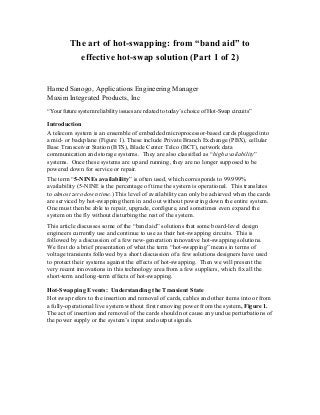
Hot swap refers to the insertion and removal of cards, cables and other items into or from
a fully-operational live system without first removing power from the system, Figure 1.
The act of insertion and removal of the cards should not cause any undue perturbations of
the power supply or the system’s input and output signals.
2. Figure 1: Multi-PCB Chassis Based System (Courtesy SPM BU)
When a fully operational chassis-based system has all its plug-in cards in the chassis,
these cards are all powered. This means that each card has all its bulk and bypass
capacitors fully charged. The bulk capacitor at the input of the supply allows the power-
supply designer to provide good power quality to the downstream regulators on the card
as well as to be able to replenish the charge on the smaller distributed bypass capacitors
which support the transient demand of the load. When a new card (no stored charge in the
on-board capacitors) is plugged into the live backplane, there is the sequence of events
that take place (Figure 2).
Figure 2: Sequence of Board Insertion and Inrush Current at Power-up
The bypass and filter storage bulk capacitors of the newly-powered PCB, act like a short
and quickly start to charge. Some of this charge comes from the live system (capacitors
C1, C2, and C3). (The already charged caps from the other cards will all discharge as a
result). This uncontrolled charging (or discharging) of the already inserted card creates a
large inrush current into bulk capacitor of the newly inserted card. Depending on the
3. system, the inrush current can reach magnitudes of hundreds of amperes during very
short amounts of time.
As the capacitors quickly charge, they appear as a short and instantaneously draw a large
amount of current. Figure 2 (right) shows a plot of the inrush flowing into a bulk
electrolytic capacitor and the voltage across the capacitor as it charges. As shown in the
lot, the peak current reaches 9.44 A. This inrush current produces a large demand on the
system and can cause the chassis system’s capacitors to discharge. The discharge event
results in a voltage drop, possibly causing the adjacent cards to reset, which, in turn,
could induce an error in the transmitted data, or cause other system glitches.
The magnitude of the instantaneous surge current is function of the load (early power)
capacitance. The larger the load’s capacitors (and the lower their ESL’s and ESR’s), the
higher are the peak inrush currents.
Impact of Voltage transients on the systems can be catastrophic
As is the case for any system, the power supplies in these chassis-based systems are
current limited. The voltage transients that occur during a hot-swap event can have large
impacts on the cards plugged into the chassis. The inrush phenomenon can result in a
significant collapse of the chassis supply rail, a voltage drop on the backplane power bus,
and/or power-supply glitches that could inadvertently generate system resets.
In addition, this unrestricted current surge can also cause physical damage to the
components, including the destruction of the card’s bypass and bulk capacitors, opens on
printed circuit board traces or backplane connectors’ pins, as well as the blowing of fuses
(which can be a major nuisance).
What happens quite often is a drop in the backplane’s power bus, which causes power
perturbations or supply glitches of the cards plugged into the system. The adjacent cards
could either get unwanted resets or the communication signaling on the backplane
(between cards) could be affected (e.g.; a bit error is induced).
Backplanes generally use differential buses (LVDS/LVPECL/Fiber Channel/ others),
which have to meet certain signaling specifications to insure proper signaling
performance. A hot-swapping event can affect their common-mode noise specifications
in the form of voltage variations on the Vcc and ground planes. Thus, a well-
implemented hot-swap circuit is one that insures that the hot-swap event does not
generate noise on the backplane large enough to cause error on the data being carried on
these backplanes.
Another problem often ignored is the long-term reliability of the system. Poorly designed
hot-swap protection circuits cause components to be slowly stressed by each induced hot-
plug event. Every time a hot-swap event takes place, its effects are like an attempt to
“pull (in order to detach)” the bond wire from the silicon within the silicon. It is this
repeated stress which causes catastrophic failure over time. The best remedy to this
phenomenon is to control peak current and inrush current on hot-swap cards.
“Band Aids” for Inrush Control
There are several known ways of implementing an inrush peak current control solution.
Some are based on sound engineering analysis, while others are a means just to mitigate
4. the effects of hot-swapping in their systems without necessarily understanding the details.
The latter are described below as “band aid” type hot-swap circuit implementations.
1) Pre-charger pin or “early power” (also know as the resistor approach)
One way to achieve inrush current control in an application is with the use the “staggered
pins” approach, also known as “early-power pins” or “pre-charge voltage” or “pre-
leading” pins. The staggered pins implementation provides a physical means to ensure
that the “new” card has been correctly seated, as well as to insure that the connections
were made in a timely and sequential fashion. This approach can also be used in
combination with a resistor to limit current during the hot-swapping event.
The pre-charge pin solution constitutes one of the most basic implementation approaches
to hot swap protection. In this approach, a combination of long and short power pins are
in the connector (Figure 3). The long power pin mates first and starts charging the “new”
card’s filter and bulk capacitors through a series resistor, Rpre-charge. This series resistor
limits the current drawn. A few milliseconds later, near the end of the physical card
seating process, the short power pin mates, bypassing the Rpre-charge series resistor and
creates a low-impedance path for powering the card. The signals pins usually the shortest
so that they will mate last to complete the seating process.
Figure 3: Smart Connectors Enable Hot Plug Capabilities
The protection device in this case is a resistor, Rpre-charge. It protects the card by limiting
the inrush current to a level which will not damage the pins or disturb the voltage rails on
the adjacent cards. Some engineers add an inductor and/or a diode to ground to this basic
implementation.
This pre-charge pin approach is a “band aid” hot-swap solution because the bulk input
filter capacitors’ charge rate is still impossible to control with this approach. There are
two main issues with this scheme: The “variations in the length of the short pins relative
to the long pins and the “fast versus slow insertion time” of the card into the system by
the service technician.
Since this is a mechanical solution, pins of the same nominal length may not necessarily
make contact at exactly the same time due to the mechanical tolerances of the connectors,
5. resulting in the variations previously mentioned. The combination of the short power pin
being a bit longer and a very fast insertion time of the PCB into the chassis may result to
the pre-charge resistor, Rpre-charge, being shorted out before the bulk input capacitor has
the chance to fully charge, thereby partially defeating the intention of controlling inrush
current.
Another important step is the sizing the Rpre-charge. This is not an easy task and can impact
the system if the size is not properly selected. The value of this pre-charge resistor has to
be sized to equalize both the pre-charge and main inrush currents. Lastly, the staggered
pin implementation requires a specialized connector, which has historically been cost
prohibitive for many systems.
As one can see from above arguments, the shortcomings of using the pre-charge pin
scheme are that it is very limited and difficult to implement with a certain level of
precision. The pre-charge pin scheme does nothing to regulate current at start-up, nor
does it provide such functions as output over-voltage and under-voltage monitoring.
2) Thermistor (current-time characteristic) approach
Another hot-swap circuit approach that embedded board-level designers have used over
the years is a thermistor-based hot-swap protection circuit. Thermistors exhibit a
significant change in resistance with a change in their body temperature (change in
resistance as a function of heat). Such components are commonly used in circuits where
temperature-dependent regulation is needed.
The negative temperature coefficient (NTC) of the thermistor’s current-time characteristic
depends on its heat capacity and dissipation constant as well as the circuit in which it is
used. It is this current-time characteristic which can be used to discriminate against high
voltage spikes of short duration and against initial current surges. Figure 4 shows a
thermistor-based, hot-swap current-limiting circuit based on the Maxim MAX4370 and an
external MOSFET [1]
.
Figure 4: Thermistor Based Hot-swap Circuit Implementation [1]
6. In the thermistor-based solutions, proper consideration must be given to the peak
instantaneous power applied to the thermistor. Some issues which the designer has to be
able to deal with are: The circuit board’s environmental temperature variations (copper
area and airflow), and the fact that the thermistor device itself may be damaged if its
voltage and/or current ratings are exceeded.
In the telecom industry where a card is not expected to be re-designed during its lifetime
after the initial release of the system to telecom carriers, a thermistor can cause a long-
term reliability issue. Another important issue to take into account is the reaction time of
the NTC. Another closely-related problem with the thermistor implementation is that if
the card is repeatedly inserted and removed in/out of the chassis, the thermistor may not
have cooled off enough to limit inrush current effectively on the next event.
Furthermore, the characteristics of the thermistor will most likely change over time
making the system vulnerable. While this approach can do a good job in temperature-
dependent regulation applications (e.g.; LCD bias supplies), the thermistor-based hot-
swap circuit does not offer the extended features of a hot-swap implementation beyond
limiting peak current.
3) Discrete hot-swap circuits
Yet another means of achieving inrush current control is via an implementation which
uses discrete components (OK, many may not considered this a “band aid” solution).
Usually, the fault protection, circuit breaker, and current control functions are all done in
independent circuits via separate power MOSFETs, power sense resistors, and other
discrete biasing components. These discrete hot-swap circuits can not only be complex
and hard to debug (increased design and validation time), but can also have higher costs
in terms of IC counts and PCB real estate.
The key issue with discrete hot-swap circuits is the impact of the effects of the parasitic
elements of the passive discrete components. These circuits use resistors and capacitors
to control the rise and fall times, voltages and currents, and other sensing conditions. The
designer has the non-trivial task of paying special attention to the manner in which the
parasitic elements affect the operating conditions of their circuit.
The best way to insure that the design’s long term protection and reliability are preserved
is to use a complete and integrated hot-swap solution. Such a solution embeds all the hot-
swap features and functions into a single monolithic die. Maxim, for example, offers a
complete portfolio of highly-integrated hot-swap solutions that deliver some of the best
performance in the industry. But Maxim is not alone – there are other integrated hot-swap
solutions from other vendors as well.
Part 2 of this article will look at a look at some of the industry’s most innovative hot-
swap solutions, including the MAX5961[2]
.
References
[1] Application Note 1785, “Flexible Hot-Swap Current Limiter Allows Thermal
Protection”, Maxim Integrated Products, available at http://www.maxim-
ic.com/appnotes.cfm/an_pk/1785
[2] A complete product brief for the MAX5961 can be found at http://www.maxim-
ic.com/quick_view2.cfm/qv_pk/5853
7. [3] Application Note 2736, “Understanding, Using, and Selecting Hot-Swap
Controllers”, Maxim Integrated Products, available at http://pdfserv.maxim-
ic.com/en/an/AN2736.pdf
Acknowledgment
The author would like to thank Dennis Wommack and Dwight Larsen for their assistance
in capturing the scope images and creating the Hot-Swap IC table, respectively.
About the Author
Hamed M. Sanogo is an applications engineering manager with Maxim Integrated
Products. He graduated from the University of Alabama at Birmingham (UAB), and then
earned an MSEE at the University of Michigan (Dearborn) and an MBA in technology
management at the University of Dallas Graduate School of Management. Before joining
Maxim, Hamed was a senior staff design engineer for Motorola, working on hot-swap
enabled embedded telecomm cards for cellular base-transceiver stations (BTS) in
Motorola’s UMTS, CDMA, and WiMax systems. Hamed can be reached at
hamed.sanogo@maxim-ic.com.