30 years poly-ceramic rotors and water lubricated screw
US6287084
1. (12) United States Patent
Kirsten
US006287084B1
(10) Patent N0.:
(45) Date of Patent:
US 6,287,084 B1
Sep. 11, 2001
(54) COMPRESSOR ASSEMBLY
(75) Inventor: Guenter Kirsten, Crimmitschau (DE)
(73) Assignee: KT Kirsten Technologie-Entwicklung
GmbH, Gornsdorf (DE)
( * ) Notice: Subject to any disclaimer, the term of this
patent is extended or adjusted under 35
U.S.C. 154(b) by 0 days.
(21) Appl. No.: 09/462,377
(22) PCT Filed: Jul. 7, 1998
(86) PCT No.: PCT/EP98/04207
§ 371 Date: Jan. 7, 2000
§ 102(e) Date: Jan. 7, 2000
(87) PCT Pub. No.: WO99/02863
PCT Pub. Date: Jan. 21, 1999
(30) Foreign Application Priority Data
Jul. 10, 1997 (DE) .............................................. 197 29 498
(51) Int. Cl.7 ...................................................... F04B 39/04
(52) US. Cl. .............................................................. 417/228
(58) Field of Search ..................................... 417/228, 313;
210/743, 177, 181, 96.1, 167, 416.3
(56) References Cited
U.S. PATENT DOCUMENTS
4,064,047 * 12/1977 Bernreiter et al. ............... .. 210/96 R
5,145,585 * 9/1992 Coke .................................. .. 210/695
5,230,810 * 7/1993 Clark et al. ........................ .. 210/743
5,466,367 * 11/1995 Coate etal. . 210/96.1
5,540,836 * 7/1996 Coyne ....... .. .. 210/221.2
5,855,791 * 1/1999 Hays et a1. ........................... 210/696
* cited by examiner
Primary Examiner—Charles G. Freay
Assistant Examiner—W Rodriguez
(74) Attorney, Agent, or Firm—Diller, Ramik & Wight
(57) ABSTRACT
A compressor system With a Water-injection cooled com
pressor (12) in a cooling Water circuit comprises a measur
ing device (30) in the cooling Water circuit (20) to determine
the conductivity of the cooling Water, a Water supply source
(40) to supply non-desalinated Water and desalinated Water,
and a controlling means (70). The controlling means (70)
causes the introduction of desalinated Water and of non
desalinated Water. The controlling means (70) causes the
introduction of desalinated Water, When the conductivity
exceeds an upper conductivity limit, and the introduction of
non-desalinated Water, When the conductivity falls beloW a
loWer conductivity limit, from the Water supply source (40)
into the cooling Water circuit (20). Thereby, the pH-value
and the salinity of the cooling Water are controlled such that
corrosion by and deposition in the cooling Water are
reduced.
10 Claims, 1 Drawing Sheet
TD?"23 21.
22
2.
3. US 6,287,084 B1
1
COMPRESSOR ASSEMBLY
BACKGROUND OF THE INVENTION
The present invention refers to a compressor system With
a Water-injection cooled compressor in a cooling Water
circuit.
Such compressor assemblies are employed to compress
gaseous media, especially air, and to provide this as a
pressure gas. Water is used for sealing, lubricating and
cooling the compressor, Which has the advantage over oil not
to be detrimental to health or the environment. DE 44 47 097
describes a Water-cooled compressor system in Which the
compressor is formed as a screW-type compressor. The
cooling Water is injected in the area of the rotors of the
compressor and reseparated from the compressed gas after
leaving the compressor. The Water heated in the compressor
is then guided toWards a cooling means. Then the cooled
cooling Water is ?ltered and re-supplied to the compressor.
In this process, various parameters of the cooling Water can
be changed by evaporation of the cooling Water or by
absorption of humidity from the air into the cooling Water:
if the relative salinity of the Water increases because of
evaporation of cooling Water, an increased amount of
deposit precipitates, Which might cause damages and defects
in the narroW sealing gaps and to the sealing rings. Deposit
formation is kept loW by a polariZation means, Which does
not, hoWever, prevent the salinity from rising. If, on the
other hand, the salinity of the cooling Water decreases
because of humidity absorbed from the air, the buffer ability
of the cooling Water to absorb free carbon dioxide is
reduced. Yet free carbon dioxide in the cooling Water Which
is not buffered (bound) is very aggressive and corrosive. The
Ph-value of the cooling Water might also be changed by
evaporation of cooling Water, absorption of humidity from
the air into the cooling Water or absorption of copper or iron
ions, so that the cooling Water has a corrosive effect.
From DE 821 993 and US 722 524, compressors are
knoWn that use distilled Water for cooling. Distilled Water is
rather expensive and is very delicate With a vieW to its pH
value.
SUMMARY OF THE INVENTION
It is the object of the invention to improve the Water
quality in an injection-cooled compressor system.
In a compressor system according to the invention, the
cooling Water circuit is provided With a measuring device to
determine the values of conductivity of the cooling Water
and a Water supply source to supply non-desalinated Water
and desalinated Water, i.e. non-deioniZed and deioniZed
Water. Acontrolling means causes the introduction of desali
nated Water, When the conductivity exceeds an upper con
ductivity limit, and the introduction of non-desalinated
Water into the cooling Water circuit, When the conductivity
falls beloW a loWer conductivity limit. Thus, the salinity of
the cooling Water is controlled such that the conductivity of
the cooling Water alWays remains Within a predetermined
range. As the conductivity also is an approximation for the
pH-value of the Water, the pH-value of the cooling Water can
be controlled such that it does not shift into the acid or
alkaline range but remains Within the neutral range by
controlling the conductivity of the Water.
When the conductivity falls beloW the loWer conductivity
limit, non-desalinated Water is added to the cooling Water,
thereby increasing the conductivity of the cooling Water so
that the value of conductivity of the cooling Water again rises
above the loWer conductivity limit. By controlling the con
10
15
25
35
45
55
65
2
ductivity of the cooling ?uid to be above a loWer conduc
tivity limit, a strong decline in the pH-value of the Water is
avoided. Thereby, the pH-value of the Water is maintained
above a pH-value of 6.5, for example. Thus, the cooling
Water is not aggressive, so that the corrosion because of the
cooling Water Within the coolant circuit is greatly reduced.
When the upper conductivity limit is exceeded, desali
nated Water is added to the cooling Water. Thereby, the
conductivity of the cooling Water is reduced. After the
conductivity falls beloW the upper conductivity limit, the
introduction of desalinated Water is stopped again. By means
of the salts dissolved in the cooling Water, the cooling Water
can absorb carbon dioxide, Which is absorbed When air is
compressed and has a very corrosive effect. The salinity of
the cooling Water, hoWever, is not arbitrary, as the salts start
to deposit When a certain concentration of salts is exceeded,
i.e., particles form in the cooling Water, Which can lead to
damages in sealing gaps, bearing seals, sliding bearings etc.
Therefore, the salinity of the cooling Water has to be limited,
Which is determined by the upper conductivity limit.
Thus, tWo effects are achieved by controlling the conduc
tivity of the cooling Water Within a determined range of
conductivity: ?rstly, a super-acidity of the cooling Water is
avoided, thereby in turn avoiding corrosion Within the
cooling Water circuit. Secondly, the salinity of the cooling
Water is maintained beloW a limit so that no deposition
occurs, Whereby damages or defects of movable parts Within
the cooling circuit can be avoided. Thereby compressor
systems can be put into practice in Which less corrosion
resistant materials can be used in the cooling Water circuit
and in the compressor. As the cooling Water is nearly free of
deposits, a compressor can be designed With very narroW
sealing gaps, and therefore, for example, With sliding bear
ings. Thus, the cooling Water control means according to the
invention provides the preconditions for increasing the
effectivity and longevity of a gas compressor system.
Preferably, the Water supply source comprises a desalin
iZation device Which is supplied With non-desalinated Water.
Furthermore, a bypass is provided bypassing the desaliniZa
tion device, and valves are provided connecting either the
desaliniZation device or the bypass to the compressor. The
valves are sWitched such that Water desalinated in the
desaliniZation device is supplied to the compressor or the
cooling circuit When the conductivity falls beloW a loWer
limit. If non-desalinated Water is to be supplied to the
cooling circuit, the valves are sWitched such that the non
desalinated Water is guided past the desaliniZation device
through the bypass and supplied to the compressor or the
cooling Water circuit in a non-desalinated state. The non
desalinated Water supplied to the desaliniZation device or the
bypass can, for example, be drinking Water from the public
drinking Water net. Preferably, the desaliniZation device is
provided as an ion exchanger or a reversed osmosis device.
The overall control of the conductivity can occur in the
form of a ?icker control or continuously. Preferably, the
conductivity can be controlled in a range from 10 to 20
pS/cm at 25° C.
In a preferred embodiment, there is provided a return pipe
from the cooling Water circuit to a Water supply source inlet
through Which Water of the cooling Water circuit can be
supplied to the Water supply source. The cooling Water
coming from the cooling Water circuit can be desalinated in
the desaliniZation device of the Water supply source When
needed. This results in a closed coolant circuit the cooling
Water thereof is desalinated in a leg parallel to the compres
sor in the desaliniZation device and resupplied to the cooling
4. US 6,287,084 B1
3
Water circuit. Thus, the cooling Water is recycled. Only little
strain is put on the desaliniZation device by not desalinating
Water supplied from the outside, e.g. drinking Water, as the
Water of the cooling Water circuit generally only has to be
desalinated to a relatively small extent.
In a preferred embodiment of the invention, the Water of
the Water supply source is led into a gas take-in duct of the
compressor. Thus, Water coming from the Water supply
source is not led into the cooling Water circuit, Which
approximately provides the pressure of the gas compressed
by the compressor, but is led into the gas take-in duct of the
compressor Where there is an approximately atmospheric
pressure. In this manner, an introduction of the Water of the
Water supply source into the cooling Water circuit can be
achieved Without a compression thereof.
In a preferred embodiment, the compressor comprises
sliding bearings, the Water of the Water supply source being
injected directly into the sliding bearings. The injection of
Water into the sliding bearings is performed before the
compressor starts Working. Thus it is ensured that the sliding
bearings are ?lled With Water, i.e. are lubricated, When the
compressor starts Working. An abrasion-intensive mixed
friction involving dry friction and sliding friction When the
compressor starts Working can thereby be avoided. After the
compressor starts Working, the pressure in the cooling
circuit increases to the compressor pressure. That is Why the
Water coming from the Water supply source, Which only has
a slight excess pressure, cannot be led directly into the
cooling Water circuit any more. Therefore, the Water coming
from the Water supply source is led into the gas take-in duct
after the compressor starts Working.
In a preferred embodiment, the cooling Water circuit
provides a temperature sensor to compensate for the tem
perature When measuring the conductivity. As the conduc
tivity of Water strongly depends on the temperature, a
temperature compensation of the measured conductivity is
required for a normaliZed measurement. Therefore, the
temperature sensor is arranged near the position of the
conductivity sensor.
Preferably, the Water supply source is connected to the
drinking Water net. Thereby, non-desalinated Water to be
supplied to the Water supply source is available at any place
of installation, by means of Which Water the salinity and
therefore the conductivity of the cooling Water can be
increased. The system Water pressure of the drinking Water
net is suf?cient to supply the Water to the Water supply
source and to inject it, in a non-desalinated or desalinated
state, into the gas take-in duct or, before the compressor
starts Working, into the compressor.
An embodiment of the invention Will noW be described in
detail With reference to the draWing.
BRIEF DESCRIPTION OF THE DRAWINGS
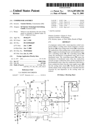
The FIGURE is an illustration of a compressor system 10
for generating oil-free pressure air.
DESCRIPTION OF THE PREFERRED
EMBODIMENT
The compressor system 10 includes a compressor 12
driven by an electric motor 13 and provided as a Water
injection cooled screW-type compressor. The screW-type
compressor 12 draWs in air via a gas take-in duct 14 and
compresses it to approximately 8 to 10 bars. The air com
pressed in the compressor 12 is led into a precipitation or
settling vessel 16 from Which it can be taken out via a
pressure air conduit 18 for further use.
10
15
25
35
45
55
65
4
The compressor system 10 comprises a cooling Water
circuit 20 in Which the cooling Water cooling the compressor
12 is cooled and puri?ed. During compression, the cooling
Water is injected in the area of the rotors of the screW-type
compressor via Water injection noZZles to seal the sealing
gap in the compressor 12 and to absorb and dissipate the heat
produced during compression in the compressor 12.
The cooling Water is reseparated from the pressure air in
the settling vessel 16 and led to a cooling means 24 via a
cooling Water conduit 22. In the course of the cooling Water
conduit 22 betWeen the settling vessel 16 and the cooling
means 24, a particulate ?lter 26 is arranged in Which
impurities and ?ne particles are ?ltered out of the cooling
Water. The cooling Water ?oWs on to the cooling means 24
in Which the cooling Water heated in the screW-type com
pressor 12 is cooled again. After that, the cooled cooling
Water passes through a polariZation means 27 in Which the
voltage occurring betWeen tWo electrodes transforms the
natural minerals dissolved in the cooling Water into the
corresponding hydroxides, thereby avoiding precipitations
and incrustations. In the further course of the cooling Water
conduit 22, there are arranged a temperature sensor 28 and
a conductivity sensor 30. The cooling Water passing the
conductivity sensor 30 ?oWs on through the cooling Water
conduit 22 to the compressor 12, in Which it is injected via
noZZles in the area of the rotors of the screW-type compres
sor 12 on the one hand, and via a bearing conduit 32 into
sliding bearings of the screW-type compressor 12 on the
other hand. In the course of the bearing conduit 32, a re?ux
valve 34 and a current relay 36 are arranged.
Cooling Water can be drained from the cooling Water
conduit 22 via a drain pipe 23 With a drain valve 24, When
too much cooling Water circulates in the cooling Water
circuit 20.
ApH-value sensor 31 is provided on the settling vessel 16
measuring the pH-value of the cooling Water in the settling
vessel 16.
The compression system 10 further comprises a Water
supply source 40 Wherefrom recycled Water can be supplied
to the cooling Water When required. The Water supply source
40 serves to provide desalinated and non-desalinated Water
Which is introduced into the coolant circuit 20 via an outlet
42 of the Water supply source 40.
Water from a conduit 46 connected to the drinking Water
net or cooling Water from a branch conduit 48 is optionally
fed to the Water supply source 40 via a supply conduit 44.
The branch conduit 48 branches betWeen the polariZation
means 27 and the temperature sensor 28 from the cooling
Water conduit 22 so that a part of the cooling Water can be
deviated via the branch conduit 48 bypassing the compressor
12 to the Water supply source 40. Acontrol valve 50, a re?ux
valve 34 With a passage toWards the Water supply source as
Well as a particulate ?lter are arranged in the course of the
branch conduit 48. The drinking Water conduit 46 comprises
a stop valve 52 and also a re?ux valve 34 continuous
toWards the direction of the Water supply source 40.
The drinking Water conduit 46 and the cooling Water
branch conduit 48 discharge into the supply conduit 44 in the
course of Which a further particulate ?lter 35 is arranged.
The supply conduit 44 ?nally discharges into a desaliniZa
tion device 54, Which can be formed as a mixed bed ion
exchanger. The desaliniZation device 54 can also be formed
as a reversed osmosis device. In the mixed bed ion
exchanger 54, strongly acid and strongly alkaline exchang
ers are employed Which WithdraW almost all the cations and
anions from the Water to be treated. The Water thus
5. US 6,287,084 B1
5
deionized, i.e. desalinated, has a conductivity of about 0.1
pS/cm to 0.2 pS/cm at 25° C. Thus, the supplied non
deioniZed Water is deionized by the desaliniZation device 54,
ie desalinated to more than 90%. Therefore, the deioniZed
Water exiting from an output conduit 55 of the desaliniZation
device 54 has a loW salinity and therefore a loW conductivity
as Well as a loW pH-value.
A control valve 56 is arranged in the course of the
desaliniZation output conduit 55, by means of Which the
output conduit 55 may be opened or closed.
A bypass 58 is provided parallel to the desaliniZation
device 54, Which bypass connects the supply conduit 44 of
the Water supply source 40 to the output conduit 42 of the
Water supply source 40, bypassing the desaliniZation device
54. In the course of the bypass 58, there also is arranged a
control valve 60. The Water ?oWing toWards the Water
supply source 40 through the drinking Water supply conduit
44 or the cooling Water branch conduit 48 can be led either
through the desaliniZation device 54 or past the desaliniZa
tion device 54 directly to the output conduit 42 according to
the position of the valves 56,60.
The output conduit 42 in turn branches into tWo branch
conduits: ?rstly, the output conduit 42 is connected to the
bearing conduit 32 of the cooling circuit 20 via a connection
conduit 62 and discharges upstream of the current relay 36
into the bearing conduit 32. In the connection conduit 62,
there is also provided a re?ux valve 34 the direction of
passage thereof has been chosen to be the direction toWards
the bearing conduit 32. Secondly, an inlet conduit 64 leads
from the output conduit 42 of the Water supply source 40 to
a Water inlet 65 in the air take-in duct 14. In the course of
the inlet conduit 64, there also is provided a re?ux valve 34
as Well as a control valve 66.
A pH-sensor 31 can be used to measure the pH-value in
the settling vessel 16. HoWever, the results obtained by
measuring the pH-value are not alWays reliable and can
therefore not be used as the primary control variable.
The membrane ?lters 26 prevent an unchecked develop
ment of germs in the cooling system and in the desaliniZa
tion device 54.
All four control valves 50,56,60,66 are controllable, i.e.
sWitchable, by a controlling means 70 via electric control
lines 68. The four sensors 26,28,30,36 of the compressor
system 10 are connected to the controlling means 70 via
measuring lines 72, so that the measuring data of the sensors
26,28,30,36 are received and inputted by the controlling
means 70.
During the operation of the compressor 12, the cooling
Water circulating in the cooling Water circuit 20 is subject to
a lot of in?uences Which keep changing the composition and
the properties of the cooling Water. Chemical, electrochemi
cal as Well as physical processes are responsible for this.
Thereby, especially the pH-value as Well as the salinity of
the cooling Water are changed. For example, in the summer
months and especially in tropical regions, a lot of the
humidity in the air taken in precipitates as a condensate,
Which gets into the cooling Water circuit in the compressor
12 and in the settling vessel 16. Thereby, the cooling Water
might be diluted With respect to its salinity, so that the
relative salinity of the cooling Water is reduced. HoWever,
When very dry cold air is compressed, evaporated Water can
be WithdraWn from the cooling Water and be absorbed and
dissipated by the compressed heated air. Thereby, the rela
tive salinity of the Water is increased. A salinity Which is too
high leads to a deposition, ie a precipitation of deposits in
the cooling Water. The deposits can cause damages or
10
15
25
35
45
55
65
6
defects to sealing gaps, seals, valves etc. of the compressor
12. If the salinity is too loW, the buffer ability of the cooling
Water With respect to the absorption of carbon dioxide
contained in the air taken in is reduced. If the buffer ability
of the cooling Water is loW, not enough carbon dioxide can
be absorbed from the compressed air. The free carbon
dioxide not buffered in the cooling Water in turn loWers the
pH-value, i.e., the cooling Water acquires aggressive, cor
rosive properties.
A cooling Water Which is as neutral as possible What the
corrosion is concerned should have a pH-value of about 7.
In no case, hoWever, should the pH-value be outside of the
range betWeen 6.5 and 7.5, as corrosion can occur even at
these values.
Generally, the salinity of Water is determined by measur
ing the conductivity of the Water. In the present example, the
conductivity of the cooling Water should alWays be betWeen
10 and 20 yS/cm (at 25° C.). The conductivity is measured
by the conductivity sensor 30 and received, evaluated and
converted into corresponding control measures and instruc
tions by the controlling means 70.
The value of conductivity measured by the conductivity
sensor 30 is compensated, i.e. normaliZed, in the controlling
means 17 according to the temperature measured by the
temperature sensor 28. This is necessary as the conductivity
of the Water depends highly on the temperature.
If the upper conductivity limit of 20 yS/cm is exceeded,
the controlling means 70 opens the control valve 56 in the
output conduit 55 of the desaliniZation device 54. Thereby,
non-desalinated Water can ?oW through the supply conduit
44 and the desaliniZation device 54 and be desalinated. The
desalinated, i.e. deioniZed Water ?oWs via the Water supply
source output conduit 42 and the inlet conduit 64 to the
Water inlet 65 Where the desalinated Water is introduced into
the air take-in duct 14. The desalinated Water thus intro
duced gets into the compressor 12 together With the air taken
in and is ?nally reseparated from the compressed air in the
settling vessel 16. By this route, it gets back into the cooling
Water circuit 20, Where it changes the salinity. This Way,
desalinated Water is introduced into the cooling Water circuit
20 until the conductivity measured by the conductivity
sensor falls back again beloW the upper conductivity limit of
20 pS/cm.
If the value falls beloW the loWer conductivity limit of 10
pS/cm, the non-desalinated Water from the drinking Water
conduit 46 is not led via the desaliniZation device 54 but via
the bypass 58 directly to the output conduit 42 by opening
the control valve 60. The non-desalinated Water is then also
introduced into the gas take-in duct 14 via the inlet conduit
64.
If the value falls beloW the loWer conductivity limit of the
Water supply source 40 and desalinated Water has to be
available, either the drinking Water from the conduit 46 or
the cooling Water led through the branch conduit 48 can be
desalinated. If the upper conductivity limit is exceeded, i.e.,
if the salinity in the cooling Water increases in an undesired
manner, in the case of a normal operation, the cooling Water
introduced via the branch conduit 48 of the Water supply
source 40 is desalinated. In this process, little strain is put on
the desaliniZation device 54, and the periods for its regen
eration are prolonged. The inlet of Water to the Water supply
source 40 is controlled by correspondingly controlling the
control valves 50,52 of the drinking Water conduit 46 and the
branch conduit 48.
The pH-value sensor 31 continuously measures the
pH-value of the cooling Water in the settling vessel 16. If the
6. US 6,287,084 B1
7
pH-value falls below 6.5, the water supply source 40 sup
plies non-desalinated water to the cooling water circuit, until
the pH-value exceeds 6.5 again. However, if the pH-value
exceeds 7.5, water desalinated in the desaliniZation device
54 is supplied to the cooling water circuit 20. The pH-value
is, however, always only corrected to such an extent as to
maintain the preset conductivity of the cooling water. This
means that maintaining the preset conductivity has priority
over controlling the pH-value.
Before the compressor 12 starts working, i.e., before the
rotors start rotating, the sliding bearings of the compressor
12 have to be ?lled with water in order to avoid an
abrasion-intensive mixed friction when the compressor
starts working. However, the sliding bearings cannot be
?lled with water from the cooling water circuit 20, as the
cooling water circuit 20 is not yet pressuriZed.
In order to ?ll the sliding bearings of the compressor 12
before the compressor 12 starts working, the drinking water
supplied by the drinking water conduit 46 is used, which
water generally has a pressure of about 3.5 bars. The
drinking water is prepared in the water supply source 40 in
a known manner such that it has a conductivity in the range
from 10 to 20 pS/cm approximately. It is only after the
sliding bearings of the compressor 12 have been ?lled with
water in this manner that the rotors of the compressor 12 can
start working.
As the working pressure of 8 to 10 bars quickly sets
within the compressor, the prepared water from the drinking
water net cannot be fed to the sliding bearings after the
compressor has started working, as the pressure thereof of
3.5 bars is too low for this purpose. Therefore, after the
compressor 12 has started working, the sliding bearings are
lubricated by the cooling water fed to the sliding bearings of
the compressor 12 via the bearing conduit 32. This is
possible as the cooling water always provides a pressure of
approximately the working pressure of the compressor 12.
As sliding bearings are very sensitive to a failure of the
water lubrication, the How towards the sliding bearings via
the bearing conduit 32 is supervised by the current relay 36.
As soon as the current relay 36 indicates that the How of the
water is too small, the controlling means 70 switches off the
motor 13, so that the rotors of the compressor 12 come to a
standstill.
If within a preset timeframe no suf?cient change in
conductivity occurs when the upper conductivity limit of 20
pS/cm is exceeded and desalinated water is added, it can be
presumed that the capacity of the desaliniZation device 54 is
exhausted. In this case, the controlling means 70 indicates
the exhaustion of the desaliniZation device 40 via a display
device (not shown) and, if necessary, switches off the motor
13 of the compressor 12.
By controlling the salinity of the cooling water via
measuring the conductivity, as has been described, a com
pressor system is provided ful?lling high demands on the
quality of the cooling water irrespective of climatic
conditions, the quality of the drinking water, the place of
installation etc. Thereby, compressors with very narrow
sealing gaps can be put into practice. Furthermore, a corro
sion of the compressor system is avoided by indirectly
controlling the pH-value of the cooling water. Therefore,
less noble and less expensive materials can be used while
increasing the service life of the system at the same time.
10
15
25
35
45
55
8
Although a preferred embodiment of the invention has
been speci?cally illustrated and described herein, it is to be
understood that minor variations may be made in the appa
ratus without departing from the spirit and scope of the
invention, as de?ned the appended claims.
What is claimed is:
1. A compressor system comprising a water-injection
cooled compressor (12) in a cooling water circuit (20),
characteriZed by
a measuring device (30) in the cooling water circuit (20)
to determine the conductivity of the cooling water,
a water supply source (40) to supply non-desalinated
water and desalinated water, and
a controlling means (70) which causes the introduction of
desalinated water, when the conductivity exceeds an
upper conductivity limit, and the introduction of non
desalinated water, when the conductivity falls below a
lower conductivity limit, from the water supply source
(40) into the cooling water circuit (20).
2. The compressor system of claim 1, characteriZed in that
the water supply source (40) comprises a desaliniZation
device (54) fed with non-desalinated water and a bypass (58)
to bypass the desaliniZation device (54), valves (56,60)
being provided either connecting the desaliniZation device
(54) or the bypass (58) to the compressor.
3. The compressor system of claim 1, characteriZed in that
a branch conduit (48) from the cooling water circuit (20) is
provided to an inlet (44) of the water supply source (40),
water from the cooling water circuit (20) being able to be
supplied to the water supply source (40) via the branch
conduit (48).
4. The compressor system of claim 1, characteriZed in that
an inlet conduit (64) leading from the water supply source
(40) into the take-in duct (14) of the compressor (12) is
provided.
5. The compressor system of claim 1, characteriZed in that
the desaliniZation device (54) is provided as an ion
exchanger or as a reversed osmosis device.
6. The compressor system of claim 1, characteriZed in that
the compressor (12) comprises sliding bearings and the
water of the water supply source (40) is connected directly
to the sliding bearings via a connection conduit (62).
7. The compressor system of claim 4, characteriZed in that
a controlling means (70) is provided, which causes water
from the water supply source (40) to be injected into the
bearing of the compressor (12) before the compressor starts
working, and to be introduced into the take-in duct (14) after
the compressor has started working.
8. The compressor system of claim 1, characteriZed in that
a temperature sensor (28) is provided in the cooling water
circuit (20) to compensate for the temperature when mea
suring the conductivity.
9. The compressor system of claim 1, characteriZed in that
the water supply source (40) is connected to the drinking
water net.
10. The compressor system of claim 1, characteriZed in
that a pH-value measuring device (31) connected to the
controlling means (70) for measuring the pH-value of the
cooling water is provided, the controlling means (70) con
trolling the water supply source (40) such that the pH-value
of the cooling water remains at approximately 7.0.
* * * * *