
Empfohlen
Weitere ähnliche Inhalte
Was ist angesagt?
Was ist angesagt? (20)
Andere mochten auch
Andere mochten auch (20)
Ähnlich wie Theory and Application of Hydraulic Ram Pumps (Hydrams) - S Hazarika
Ähnlich wie Theory and Application of Hydraulic Ram Pumps (Hydrams) - S Hazarika (20)
Mehr von Fifi62z
Mehr von Fifi62z (13)
Kürzlich hochgeladen
Kürzlich hochgeladen (20)
Theory and Application of Hydraulic Ram Pumps (Hydrams) - S Hazarika
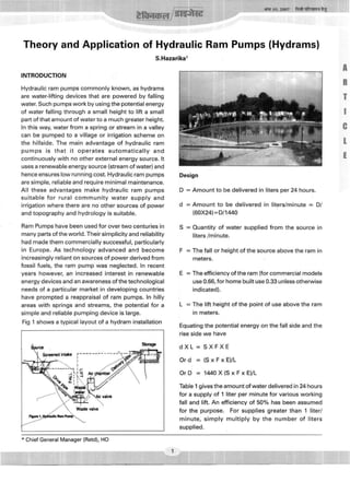
- 1. ^ftiraiH/Si^^ 3T^ 10, 2007 ft#4R^M-i%^ Theory and Application of Hydraulic Ram Pumps (Hydrams) S.Hazarika^ INTRODUCTION ": '^ "M^'":':':^-: '^^/'^i-" Hydraulic ram pumps commonly known, as hydrams are water-lifting devices that are powered by falling water. Such pumps work by using the potential energy of water falling through a small height to lift a small part of that amount of water to a much greater height. In this way, water from a spring or stream in a valley can be pumped to a village or irrigation scheme on the hillside. The main advantage of hydraulic ram p u m p s is that it operates automatically and continuously with no other external energy source. It uses a renewable energy source (stream of water) and hence ensures low running cost. Hydraulic ram pumps are simple, reliable and require minimal maintenance. All these advantages make hydraulic ram pumps suitable for rural c o m m u n i t y water supply and irrigation where there are no other sources of power and topography and hydrology is suitable. Ram Pumps have been used for over two centuries in many parts of the world. Their simplicity and reliability had made them commercially successful, particularly in Europe. As technology advanced and become increasingly reliant on sources of power derived from fossil fuels, the ram pump was neglected. In recent years however, an increased interest in renewable energy devices and an awareness of the technological needs of a particular market in developing countries have prompted a reappraisal of ram pumps. In hilly areas with springs and streams, the potential for a simple and reliable pumping device is large. Fig 1 shows a typical layout of a hydram installation Storage Design D = Amount to be delivered in liters per 24 hours. d = Amount to be delivered in liters/minute = D/ (60X24) = 0/1440 S = Quantity of water supplied from the source in liters/minute. F = The fall or height of the source above the ram in meters. E = The efficiency of the ram (for commercial models use 0.66, for home built use 0.33 unless otherwise indicated). L = The lift height of the point of use above the ram in meters. Equating the potential energy on the fall side and the rise side we have d X L = S X F X E O r d = ( S x F x E ) / L O r D = 1 4 4 0 X ( S x F x E ) / L • : ' , Table 1 gives the amount of water delivered in 24 hours for a supply of 1 liter per minute for various working fall and lift. An efficiency of 50% has been assumed for the purpose. For supplies greater than 1 liter/ minute, simply multiply by the number of liters supplied. Chief General Manager (Retd), HO
- 2. ISSUE 10, 2007 For Private circulation only TECHNICAL/liJGEST Table 1 : Working Fall (F) 4 Meters 1.0 1.5 2.0 2.5 3.0 3.5 4.0 5.0 6.0 7.0 8.0 9.0 10.0 12.0 14.0 16.0 18.0 20.0 Hydram ^HHHHH| 5.0 144 216 288 Performance - 7.5 96 144 192 240 288 336 10.0 72 108 144 180 216 252 288 360 432 Water Delivered 1 Vertical H 15.0 48 72 96 120 144 168 192 240 288 336 384 432 eight thro 20.0 36 54 72 90 108 126 144 180 216 252 288 324 360 432 504 in 24 Hours (liters) for ugh w h Met 30.0 24 36 48 60 72 84 96 120 144 168 192 216 240 288 336 384 432 480 ich wate ers 40.0 18 27 36 45 54 63 72 90 108 126 144 162 180 216 252 288 324 360 r is to be lifi 50.0 22 29 36 43 50 58 72 86 101 115 130 144 173 202 230 259 288 a Supply of 1 Lits/Min ted (L) 60.0 18 24 30 36 42 48 60 72 84 96 108 120 144 168 192 216 240 80.0 18 23 27 32 36 45 54 63 72 81 90 108 126 144 162 180 Efficiency 5 0 % 100.0 18 22 25 29 36 43 50 58 65 72 86 101 115 130 144 125.0 17 20 23 29 35 40 46 52 58 69 81 92 104 115 Design of Components of Hydraulic Ram A hydraulic ram installation consists of a supply, a drive pipe, the ram, a supply line and usually a storage tank. These are shown in Figure 1. Each of these component parts is discussed below: Supply. The intake must be designed to keep trash and sand out of the supply since these can plug up the ram. If the water is not naturally free of these materials, the intake should be screened or a settling Table 2 : Range of Drive Pipe Lengths for Various Pipe Diameters IDrive Pipe Size (mm) 13 20 25 30 40 50 80 100 Length (meters) Minimum Maximum 2 3 4 4.5 6 7.5 12 15 13 20 25 30 40 50 80 100 basin provided. When the source is remote from the ram site, a supply line can be provided to conduct the water to the drive pipe. The supply line, if needed, should be at least one pipe diameter larger than the drive pipe. Drive pipe. The drive pipe must be made of a non- flexible material for maximum efficiency. This is usually galvanized iron pipe, although other materials cased in concrete will work. In order to reduce head loss due to friction, the length of the pipe divided by the diameter of the pipe should be within the range of 150-1,000. Table 2 shows the minimum and maximum pipe lengths for various pipe sizes. I Table 3 : Sizing the Delivery Pipe Delivery Pipe Size (mm) 30 40 50 80 100 Flow liters/min 6-36 37-60 61-90 91-234 235-360
- 3. Bterascr/sR^'^ 3te 10,2007 Prat MR^HH I ^ The drive pipe diameter is usually chosen based on the size of the ram and the manufacturer's recommendations. Delivery Pipe. The delivery pipe can be of any material that can withstand the water pressure. The size of the line can be estimated using Table 3. Storage Tanl<. This is located at a level to provide water to the point of use. The size is based on the maximum demand per day. Installation In installing the ram, it is important that it be level, securely attached to an immovable base, preferably concrete, and that the waste water be drained away. The pump cannot operate when submerged. Since the ram usually operates on a 24-hour basis the size can be determined for delivery over a 24-hour period. APPLICATIONS AND LIMITATIONS OF HYDRAULIC RAM PUMPS The advantages of a ram pump are : • Use of a renewable energy source ensuring low running cost • Pumping only a small proportion of the available flow has little environmental impact • Simplicity and reliability give a low maintenance requirement • There is good potential for any particular site; there is usually a number of potential water lifting options. Choosing between them involves consideration of many different factors. Ram pumps in certain conditions have many advantages over other forms of water lifting, but in others, it can be completely inappropriate. The main advantages of ram pumps are: for local manufacture in the rural villages • Automatic, continuous operation requires no supervision or human input. The main limitations are; • They are limited to hilly areas with a year-round water sources • They pump only a small fraction of the available flow and therefore require source flows larger than actual water delivered • Can have a high capital cost in relation to other technologies • Are limited to small-scale applications, usually up to IkW Specific situations in which other technologies may prove more appropriate are: • In terrain where streams are falling very rapidly, it may be possible to extract water at a point above the village or irrigation site and feed it under gravity. • If the water requirement is large and there is a large source of falling water (head and flow rate) nearby, turbine-pump sets can provide the best solution. Many ram pumps could be used in parallel to give the required output but at powers over 2kW, turbine-pump systems are normally cheaper. • In small-scale domestic water supply, the choice can often be between using a ram pump on a stream or using cleaner groundwater. Surface water will often need to be filtered or treated for human consumption, increasing the cost of a system and requiring regular filter maintenance. Under these conditions, to select a hydram pump, economical considerations compared to other technologies has to be looked at. REFERENCES £ >: 1. Jeffery, T. D., "Hydraulic Ram Pumps - A Guide to Ram Pumps Water Supply System", Intermediate Technology Publications, ^Q22. 2. Dr. Tessema, Abiy Awoke " Hydraulic Ram Pump System Design And Application" ESME 5th Annual Conference on Manufacturing and Process Industry, September 2000