1. (12) United States Patent
Hobbs et a1.
US008529645B2
US 8,529,645 B2
Sep. 10, 2013
(10) Patent N0.:
(45) Date of Patent:
(54)
(75)
(73)
(21)
(22)
(65)
(51)
(52)
HYDROGASIFICATION REACTOR AND
METHOD OF OPERATING SAME
(58) Field of Classi?cation Search
USPC ............................................... .. 48/62 R462 A
See application ?le for complete search history.
Inventors: Raymond Hobbs, Avondale, AZ (US); _
Donald Karner, Phoenix, AZ (US); (56) References Clted
Xiaolei Sun, Chandler, AZ (US); John
Boyle’ Emmaus’ PA (Us); Fuyuki U.S. PATENT DOCUMENTS
Noguchi, Hyogo (JP) 2,985,324 A * 5/1961 Balentine .................... .. 414/217
4,153,426 A * 5/1979 Wintrell .... .. 48/73
' . - - - 4,610,697 A * 9/1986 Darling et a1. 48/77
Asslgnee' 35mm glgbhcssemce Company’ 2003/0174756 A1 * 9/2003 Groen 374/141
Oemx, (U ) 2006/0265953 A1 * 11/2006 Hobbs .............. .. .. 48/127.3
_ _ _ _ _ 2007/0079554 A1 * 4/2007 Schingnitz et a1. ........... .. 48/210
Not1ce: Subject to any d1scla1mer, the term of th1s * _ _
patent is extended or adjusted under 35 cued by examlner
U'S'C' 1546)) by 891 days‘ Primary Examiner * lmran Akram
NO . Attorney, Agent, 0/’ i Snell & Wilmer. .. ,
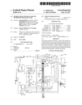
Filed: Oct. 3, 2007 (57) ABSTRACT
The present invention provides a system and method for
Prior Publication Data evaluating effects ofprocess parameters on hydrogasi?cation
processes. The system includes a hydrogasi?cation reactor, a
Us 2009/0090054 A1 Apr‘ 9’ 2009 pressurized feed system, a hopper system, a hydrogen gas
Int Cl source, and a carrier gas source. Pressurized carbonaceous
C1bJ3'/08 (2006 01) material, suchas coal, is fedto thereactorusing the carrier gas
U 5 Cl ' and reacted With hydrogen to produce natural gas.
USPC ........................................................ .. 48/62 R 17 Claims, 6 Drawing Sheets
Q9 /116 Q90". HP 100
L VENT U, K_ VENT
FILR CDMRESSOR A
o1
J.
21.1%BACK PRESSURE
REGULATOR
‘3EFILTER FILTER
llllllll
8. US 8,529,645 B2
1
HYDROGASIFICATION REACTOR AND
METHOD OF OPERATING SAME
GOVERNMENT LICENSE RIGHTS
The US. Government has a paid-up license in this inven
tion and the right in limited circumstances to require the
patent oWner to license others on reasonable terms as pro
vided for by the terms ofContract No. DE-FC26-06NT42759
awarded by the Department of Energy.
FIELD OF INVENTION
The present invention generally relates to systems and
methods for producing substitute natural gas (SNG) from
carbonaceous material. More particularly, the invention
relates to systems and methods for producing SNG using
hydrogasi?cation ofcarbonaceous material and to techniques
and systems for characterizing the hydrogasi?cation process.
BACKGROUND OF THE INVENTION
Because of their relatively high energy density and their
current availability, fossil fuels, such as coal, are currently
used to supply most of the World’s energy requirements.
Unfortunately, use of such fuels is thought to generate a
substantial portion ofthe greenhouse gas emissions. Thus, as
global demand for energy and aWareness ofpossible environ
mental damage caused by the use of fossil-fuel energy
sources increase, it becomes increasingly desirable to use
such energy sources more ef?ciently, While mitigating any
negative environmental effects.
One technique that has been developed for more ef?ciently
using coal and mitigating deleterious environmental effects
includes gasi?cation ofcoal to produce substitute natural gas
(SNG). Producing SNG from coal is desirable because the
produced SNG can be used in existing natural gas infrastruc
ture (e.g. pipelines, compressor stations, and distribution net
Works), in commercial applications Where natural gas is a
feedstock, in domestic applications Where natural gas is used
for heating and cooking, and in electric utility applications
Where natural gas is used as a fuel to produce electricity. Coal
reserves are substantially greater and more accessible than
natural gas supply, and SNG can provide an additional supply
of natural gas as the supply of existing natural gas sources
diminishes. Producing SNG from coal also has the added
advantages ofproviding stability to the supply and thus price
of natural gas, and SNG is a higher density, cleaner burning
fuel, as compared to coal.
Although some techniques for gasifying coal and the pro
duction of methane or SNG from coal are generally known,
the various reactions and associated kinetics are not neces
sarily Well understood. Accordingly, apparatus and tech
niques to study coal gasi?cation reactions, and in particular,
hydrogasi?cation reactions, are desired.
SUMMARY OF THE INVENTION
The present invention provides an improved reactor and
method for evaluating process conditions and reaction kinet
ics of hydrogasi?cation processes. While the Ways in Which
the present invention addresses the various draWbacks of the
prior art are discussed in greater detail beloW, in general, the
invention provides a system including a hydrogasi?cation
reactor With variable operation parameters and measurement
and/or test equipment to evaluate effects ofvarying operating
conditions on resultant products.
20
25
30
35
40
45
50
55
60
65
2
In accordance With various embodiments ofthe invention,
a system is con?gured to alloW manipulation ofvarious oper
ating parameters, such as reactants, reactant ?oW rates, reac
tion temperature, reaction pressure, feed particle size, feed
type, reactor residence time, gas:solid feedratio, andthe like.
In accordance With further aspects, a system is con?gured
to measure reactor temperature, reactor pressure, methane
yield, product (e.g., char) properties, and the like.
In accordance With various embodiments ofthe invention,
a reactor is con?gured as a double-Wall reactor, having an
interior Wall and an exterior Wall. A reaction occurs Within an
interior space ofthe inner Wall. In accordance With particular
aspects ofthese embodiments, pressurized gas is provided in
the space betWeen the interior and exterior Walls. The pres
surization is desirable to provide stability to the reactor during
a hydrogasi?cation process, Which generally occurs at rela
tively hightemperature andhighpressure. In accordance With
various aspects ofthese embodiments, the space betWeen the
interior and exterior Walls is pressurized to a pressure greater
than the reaction pressure Within an interior portion of the
inner Wall. Providing a pressure on an exterior surface ofthe
interior Wall that is greater than the pressure on an interior
surface of the interior (e.g., the reaction pressure) may be
desirable to contain any potential leaks ofmaterials Within an
interior portion ofthe inner Wall.
In accordance With additional embodiments, the reactor is
con?gured as a single-drop reactor.
In accordance With yet further embodiments, the reactor
includes a high-pressure fuel feed system. In accordance With
some aspects ofthese embodiments, a magnetic feeder is used
to inject a pressurized fuel (e.g., coal) stream into a reaction
area. In accordance With other aspects, a carrier gas is used to
facilitate injection of the feed.
BRIEF DESCRIPTION OF THE DRAWINGS
The exemplary embodiments ofthe present invention Will
be describedinconnectionWiththe appendeddraWing ?gures
in Which like numerals denote like elements and:
FIG. 1 schematically illustrates a system for producing
substitute natural gas and evaluating the process in accor
dance With various embodiments of the invention;
FIG. 2 illustrates a reactor in accordance With various
embodiments ofthe present invention;
FIG. 3 illustrates a cut-aWay vieW of a reactor in accor
dance With various embodiments of the invention;
FIG. 4 illustrates a cross-sectional vieW of a top portion of
a reactor in accordance With various embodiments of the
invention;
FIG. 5 illustrates an exemplary feed system for use With
various embodiments of the invention; and
FIG. 6 illustrates char hoppers and valve systems for use
With various embodiments of the invention.
Elements in the ?gures are illustrated for simplicity and
clarity and have not necessarily been draWn to scale. For
example, the dimensions of some of the elements in the ?g
ures may be exaggerated relative to other elements to help to
improve understanding ofembodiments ofthe present inven
tion.
DETAILED DESCRIPTION
The present invention provides a hydrogasi?cation reactor
and system and method ofusing the reactor and system. More
particularly, the invention provides a reactor and system for
9. US 8,529,645 B2
3
evaluating process conditions, reactants, and products of
hydrogasi?cation processes, such as hydrogasi?cation ofcar
bonaceous material(s).
The reactor and system ofthe present invention canbe used
to develop andunderstandhydrogasi?cationreactionkinetics
and understand the effects ofprocess conditions on products,
both desired and undesired, of hydrogasi?cation reactions.
The information that is obtained using the system and reactor
can, in turn, be used to design other, e.g., larger production
reactors and systems.
The reactor, system, and method of the present invention
can be used for various hydrogasi?cation processes and is
conveniently described beloW in connection With hydrogas
i?cation ofcoal. HoWever, the invention is not limited to such
fuel, and can be used to react other material(s) With hydrogen.
Exemplary process parameters that can be manipulated,
measured, and/or analyzed to determine their effects on reac
tions kinetics, feed conversion and reactant products include:
carrier gas, temperature, pressure, coal type and size, resi
dence time, hydrogen-to-carbon ratio, reactants, and the like.
As discussed in more detail beloW, hydrogasi?cation of
materials such as coal is exothermic and generally occurs at
relatively high pressures and temperatures. Accordingly, sys
tems and reactors in accordance With various embodiments of
the invention are speci?cally designed to Withstand such
operating conditions.
FIG. 1 illustrates a system 100 in accordance With various
embodiments ofthe invention. System 100 includes a hydro
gasi?cation reactor 102, a feed system 104, a hopper system
106, a hydrogen storage/supply unit 108, a Water supply and
storage unit 110, a carrier gas supply and storage unit 112, and
a purge gas supply and storage unit 114. Although not illus
trated, system 100 may also include suitable automatic shut
doWn systems.
In accordance With one exemplary embodiment, reactor
102 is designed as a single pass or single drop reactor, such
that the injected coal makes a single pass through the reactor.
HoWever, the invention is not limited to such reactor design.
In operation, system 100 produces SNG by reacting car
bonaceous material, such as crushed and pulverized coal,
With hydrogen in hydrogasi?cation reactor 102. The carbon
aceous material is fed to reactor 102 using feed system 104.
More particularly, carbonaceous material and a carrier gas
(e.g., CO2, N2, H2, or a combinationthereof) from supply 112
are fed to feed system 104 to provide pressurized feed and the
carrier gas to reactor 102. The feed is pressurized (e.g., to a
pressure greater than about 500 psi or greater than about 1000
psi) to mitigate disruption to any reaction occurring in reactor
102. As illustrated, an additional carrier gas (e.g., CO2, N2,
H2, or a combination thereof) from supply 114 may option
ally also be introduced into feed system 104 to, for example,
evaluate the effects of alternative feed and/or reactant gases.
Operating parameters may be adjusted to determine
desired operating conditions and/or effects ofthe parameters
on reaction kinetics, thermodynamics, feed conversion, and
the like. In accordance With various embodiments of the
invention, a feed rate is adjustable from about 1 to about 25 or
about 5 to about 15 lb/hour; a hydrogen feed rate is adjustable
from about 300 to about 9000 standard cubic feet per hour; a
coal to hydrogen ratio is adjustable from about 0.2 to about
0.4; a temperature is adjustable from about room temperature
(e.g., about 77° F.) up to about 19000 F. or about 12000 F. to
about 18000 F.; pressures Within the reactor can be manipu
lated from ambient pressure to about 1200 psig or about 800
to about 1200 psig; residence time of hydrogen and feed
material can be manipulated from about 5 seconds to about 50
seconds4e.g., about 5 seconds to about 40 seconds, or about
20
25
30
35
40
45
50
55
60
65
4
9 seconds to about 18 seconds; and the system can evaluate
the effects of H20 (e.g., about 0.5-3 lb/hr) and CO2 (e.g.,
about 5 to about 30 standard cubic feet/hour) additions to the
feed. Effects of various types of feed such as coal of various
sizes (e.g., about 75 to about 375 mesh; e.g., about 200 mesh
(70% pass), or about 30 to about 100 microns) can also be
tested in the reactor.
During the reaction, hydrogen is fed to reactor 102 from
source 108. The hydrogen may be ?ltered using a ?lter 118
(e.g., an in-line stainless steel mesh ?lter) and heated using
heaters 120, 122 (e.g., electric-type heaters) to a temperature
ofabout 12000 F. to about 16000 F. or about 15000 F. Note that
because hydrogen has a high thermal conductivity, heaters
120, 122 may be placed close to reactor 102 and system 100
may include ceramic insulation betWeen heaters 120, 122 and
reactor 102.
Referring noW to FIGS. 2-4, hydrogasi?cation reactor 102
is illustrated in greater detail. In the illustrated embodiment,
hydrogasi?cation reactor 102 includes a double-Walled
hydrogasi?cation chamber 202, including an inner Wall 302
and an outer Wall 304. The double-Wall con?guration alloWs
for pressurized gas (e.g., air and/or nitrogen) in an annular
space betWeen an exterior surface of inner Wall 302 and an
interior surface of outer Wall 304, Which can be regulated
using, for example, a balancing regulator 205. Reactor 102
also includes a top ?ange system 204 and a bottom ?ange
system 206 to seal the annular space and maintain a desired
pressure betWeen inner Wall 302 and outer Wall 304. A length
of reactor 102 may vary in accordance With various design
parameters. In accordance With one example, reactor 102 is
about 5 to about 20 or about 12 feet long.
Inner Wall of vessel 302 may be con?gured in a variety of
Ways, depending on, for example, desired operating tempera
tures and pressuresiboth internal and external to Wall 302.
In general, Wall 302 is con?gured to Withstand internal pres
sure greater than about 1200 psig and temperatures up to
about 19000 F. In accordance With one speci?c example, Wall
302 is formed Inconelie.g., Inconel 617 or 625 (1.8" id, 2"
od).
Similarly, outer Wall 304 may be formed in a variety of
con?gurations using a variety of materials. In accordance
With one example ofthe invention, outer Wall is 304 is formed
of schedule 80 (9.6" id, 10.8" od) 10" stainless steel and is
con?gured to Withstand pressures greater than about 1200
psig. Wall 304 may alternatively be formed ofinconel, or like
materials.
Referring noW to FIGS. 3 and 4, a top portion 301 ofreactor
102 includes a head assembly 303, a plurality ofgas injection
ports 408, and a feed inlet 410. Head assembly 303 is con?g
uredto form a seal betWeen a top ofinternal Wall 302 and a top
of outer Wall 304 and alloW for reactant input through inlet
408 and pressurized feed through inlet 410 to an interior
portion of Wall 302.
In the illustrated embodiment, input injector ports 408 are
angled relative to a centerline of the reactor. In accordance
With various aspects ofthis embodiment, ports 408 are angled
betWeen about 30 and about 70 degrees, or about 40 to about
60 degrees or about 45 to about 50 degrees relative to the
centerline through reactor 102 to reduce clogging ofthe reac
tor. A number of inlets 408 may vary in accordance With
various design parameters, but are generally about evenly
spaced from each other around a perimeter of the reactor. In
the illustrated embodiment, reactor 102 includes 4 injector
ports 408.
As illustrated in FIGS. 3 and 4, exemplary reactor 102 also
includes heaters 306, internal thermocouples 308, and exter
nal thermocouples 310. Heaters 306 are placed on an exterior
10. US 8,529,645 B2
5
surface of inner Wall 302. To facilitate rapid and control
heating of reactor 102, heaters 306 are electric heaters con
?gured to heat inner Wall to a desired temperature (e.g., up to
about 2300° F.). By Way of one example, heaters 306 are
ceramic heaters designed to heat to about 13000 F. to about
19000 F. A number of heaters may vary in accordance With
design factors and considerations. By Way of one example,
seven heaters 306 are placed along an exterior surface ofWall
302.
Thermocouples 308 are placed inside Wall 302 to measure
reactor 102 temperatures at various points along an interior
portion of inner Wall 302. In accordance With one speci?c
example, thermocouples 308 are k-type thermocouples.
Similarly, thermocouples 310 may be k-type thermocouples
and placed along an exterior surface of Wall 302 to measure
the outside Wall temperature. Thermocouples 308 may be
inserted from reactor 102 head, and thermocouples 310 may
be held in place With pads. A number ofthermocouples 308,
310 may vary in accordance With various design parameters,
such as length ofreactor 102, type ofthermocouples, and the
like. In one example of the invention, reactor 102 includes 6
thermocouple 308 and 49 thermocouples 310. In accordance
With further embodiments, at least some of thermocouples
308 and thermocouples 310 are coupled to a controller, not
shoWn, to control heaters 306 to obtain or maintain a desired
temperature. By Way of one particular example, system 100
includes seven thermocouples 310 for each heater 306, such
that tWo thermocouples are placed above, beloW and proxi
mate a heater to measure Wall 302 temperaturejust above and
beloW the heater, tWo thermocouples 310 are coupled to the
heater exterior insulation layer and a safety/shut-doWn sys
tem, tWo thermocouples 310 are coupled to a controller to
control the heater and a safety/shut-doWn system, and one
thermocouple is placed middle and proximate Wall 302 to
measure the temperature ofWall 302 in the middle position of
heater 306. The invention, hoWever, is not limited to such
con?guration.
As illustrated in FIG. 1, reactor 102 may also include an
optional feed line 130, and supply 132, Which may be used to
feed additional reactant(s) to vessel 202. For example, line
130 and supply 132 may be used to feed oxygen and/or H2O
to reactor 102 to combust With hydrogen to obtain a desired
reaction temperature for a hydrogasi?cation process (e.g.,
about l,200° F. to about l,600° F.).
Reactor 102 may also include ports, such as sealable ports
402, 404, to, for example, alloW Wiring, such as heater poWer
Wiring and thermocouple Wiring to pass through outer Wall
304.
As noted above, in accordance With various embodiments,
an annular region 406 betWeen inner Wall 302 and outer Wall
304 is pressurized to reduce an amount of stress on inner Wall
302. In accordance With one example, a pressure Within annu
lar space 406 is greater than a pressure Within inner Wall 302
(e.g., about 15 psi greater), so that if there is a leak in inner
Wall 302, pressurized annular region 406 Will cause any mate
rials Within inner Wall 302 to continue to How through reactor
102 and system 100.
Referring noW to FIGS. 1 and 5, a feeder 104 (e.g., a
magnetic feeder) includes a vessel 502, including feeder gas
inputs 504, for receiving a carrier gas, coupled to a conveyor
506, Which feeds pressurized coal and carrier gas to reactor
102. As illustrated, feeder 104 also includes a second gas
input 508 to receive additional carrier gas to facilitate injec
tion of the carrier gas/coal mixture into reactor 102 and a
motor 510 to drive conveyor 506. As illustrated in FIG. 1,
motor 510 may be cooled using Water supply 110.
20
25
30
35
40
45
50
55
60
65
6
In general, feeder 104 is designed to feed coal to reactor
102 With minimal disruption to any ongoing reaction Within
reactor 102. In accordance With one example, coal and carrier
gas are pressurized from about ambient to about 2000 psig,
about 500 to about 1800 psig, or about 600 to about 1500 psig
prior to being fed into reactor 102.
Referring again to FIG. 1, system 100 includes a cooler,
e.g., Water cooler 116 to regulate a temperature of the pres
surized feed. Cooling system 116 may be coupled to Water
supply 110 and formed of, for example, 1A" stainless steel
tubing.
Turning noW to FIGS. 1 and 6, char hopper system 106
includes a ?rst hopper 602, a second hopper 604, a valve 606
coupled betWeen hopper 602 and hopper 604, and a valve 608
coupled to hopper 604. Hopper system 106 also includes a
Water cooler 601, a ?rst outlet 612, and a second outlet 614.
System 106 may also include temperature and/or pressure
sensors located on an interior portion of hopper 602 and/or
604 to measure the temperature and/or pressure of hopper
material.
In operation, as char and gasses How to system 106 from
reactor 102, during a transient stage, valve 606 is open. Tran
sient solid residue can be collected by hopper 604 and tran
sient materials, such as product gasses, including CO, CH4,
CO2, H2, H2O, H2S, COS, C2", ole?ns, para?ins, benzene,
toluene, xylene, long-chain tars ad oils, HCl, phenolic spe
cies, and the like can be exhausted through outlet 612. Gas
eous materials may be evaluated using, for example, gas
chromatography and/or mass spectrometry. During a steady
state stage, obtained by closing valve 606, solid residue can
be collected by hopper 602. Product gases, such as CO, CH4,
CO2, H2, H2O, HZS, COS, C2", ole?ns, paraf?ns, benzene,
toluene, xylene, long-chain tars ad oils, HCl, phenolic spe
cies, and the like, can be exhausted through outlet 612 and
analyzed by using the same techniques used to analyze tran
sient materials. When a reaction is complete, solid residue
fromhopper 604 and 602 can easily be separately collected by
opening valve 608.
Referring again to FIG. 1, system 100 may also include a
cooler 134, such as a bloWer, to cool materials from reactor
102 before entering hopper system 106. System 100 may also
include coolers 124, 126, to respectively cool materials enter
ing reactor 102 and exiting reactor 102, and a heat exchanger
136 to further cool ef?uent from hopper system 106.
Although exemplary embodiments ofthe present invention
are set forth herein, it should be appreciated that the invention
is not so limited. For example, although the systems are
described in connection With various process parameters, the
invention is not so limited. Various modi?cations, variations,
and enhancements ofthe system and method set forth herein
may be made Without departing from the spirit and scope of
the present invention as set forth in the folloWing claims and
their equivalents.
What is claimed is:
1. A hydrogasi?cation system, the system comprising:
a single-pass, vertically-oriented hydrogasi?cation reac
tor, including an inner Wall, an outer Wall, a top portion,
a bottom portion, and a pressurized sealed space
betWeen the inner and outer Wall, Wherein the inner Wall
is con?gured to Withstand reaction pressure up to about
1200 psig. and Wherein the top portion includes a plu
rality ofinjectionports angledbetWeen about 30 degrees
and about 70 degrees relative to a centerline ofthe reac
tor and a feed inlet;
a hydrogen source coupled to the top portion ofthe hydro
gasi?cation reactor;
11. US 8,529,645 B2
7
a heater located between the inner Wall and outer Wall, the
heater con?gured to heat the inner Wall to a temperature
of about 13000 F. to about 19000 F.;
a feed system coupled to the top portion of the hydrogas
i?cation reactor; and
a hopper system coupled to the bottom end of the hydro
gasi?cationreactor, the hopper system comprising a ?rst
hopper comprising a ?rst outlet and a second outlet for
analysis oftransient materials, a second hopper coupled
to the ?rst outlet ofthe ?rst hopper, and a valve betWeen
the ?rst hopper and the second hopper,
Wherein the second outlet of the ?rst hopper is not
coupled to the second hopper,
Wherein When the valve is open, transient solid residue is
collected in the second hopper, and When the valve is
closed, steady-state solid residue is collected in the
?rst hopper, and
Wherein reactants enter the reactor at the top portion and
products exit the reactor at the bottom portion.
2. The hydrogasi?cation system of claim 1, further com
prising a carrier feed supply ?uidly coupled to the feed sys
tem.
3. The hydrogasi?cation system of claim 2, Wherein the
carrier feed supply comprises a material selected from the
group consisting ofnitrogen, hydrogen, carbon dioxide, and
mixtures thereof.
4. The hydrogasi?cation system of claim 3, Wherein the
carrier feed supply comprises carbon dioxide.
5. The hydrogasi?cation system of claim 2, Wherein the
carrier feed supply comprises a motor and a conveyor.
6. The hydrogasi?cation system of claim 2, Wherein the
carrier feed supply comprises a magnetically driven con
veyor.
7. The hydrogasi?cation system of claim 2, Wherein the
carrier feed supply is con?gured to provide feed pressurized
to about 2000 psig. to the reactor.
8. The hydrogasi?cation system of claim 1, further com
prising a thermocouple located on an interior portion of the
inner Wall.
9. The hydrogasi?cation system of claim 1, further com
prising a thermocouple located on an exterior portion of the
inner Wall.
10. A hydrogasi?cation system, the system comprising:
a single-pass, vertically-oriented hydrogasi?cation reactor
for reacting carbonaceous material With hydrogen, the
hydrogasi?cation reactor comprising a plurality of
hydrogen injector ports angled betWeen about 30
degrees and about 70 degrees relative to a centerline
20
25
30
35
40
45
8
through the reactor, a top portion, a bottom portion, an
inner Wall, an outer Wall, a sealed space betWeen the
inner Wall and outer Wall, and a heater Within the sealed
space, the heater con?gured to heat the inner Wall to a
temperature of about 13000 F. to about 19000 F.;
a hydrogen source coupled to the top portion ofthe hydro
gasi?cation reactor;
a hydrogen heater located betWeen the hydrogasi?cation
reactor and the hydrogen source;
a pressurized feed system to provide a feed at greater than
about 500 psig. coupled to the to portion of the hydro
gasi?cation reactor; and
a hopper system coupled to the bottom portion of the
hydrogasi?cationreactor, the hopper system comprising
a ?rst hopper comprising a ?rst outlet and a second outlet
for analysis of transient materials, a second hopper
coupled to the ?rst outlet of the ?rst hopper and the
second outlet of the ?rst hopper is not coupled to the
second hopper, a ?rst valve betWeen the ?rst hopper and
the second hopper and a second valve coupled to the
secondhopper, andWhenthe ?rst valve is closed, steady
state solid residue is collected in the ?rst hopper, and
Wherein reactants enter the reactor at the top portion and
products exit the reactor at the second end.
11. The hydrogasi?cation system ofclaim 10, Wherein the
hydrogasi?cation reactor comprises a pressurized annular
region betWeen the inner Wall and the outer Wall.
12. The hydrogasi?cation system ofclaim 11, further com
prising a material selected from the group comprising nitro
gen, air, and a combination thereof, in the pressurized annular
region.
13. The hydrogasi?cation system ofclaim 11, further com
prising a plurality of heaters interposed betWeen the inner
Wall and the outer Wall.
14. The hydrogasi?cation system ofclaim 10, further com
prising a carrier gas source coupled to the pressurized feed
system.
15. The hydrogasi?cation system ofclaim 14, Wherein the
carrier gas source comprises a material selected from the
group consisting ofnitrogen, carbon dioxide, and hydrogen.
16. The hydrogasi?cation system ofclaim 10, Wherein the
hydrogasi?cation reactor is con?gured for an operating tem
perature ofup to about 23000 F.
17. The hydrogasi?cation system ofclaim 10, Wherein the
hydrogasi?cation reactor is con?gured for an operating pres
sure of up to about 1200 psig.
* * * * *