Iai scon controller_specsheet
•
0 gefällt mir•622 views

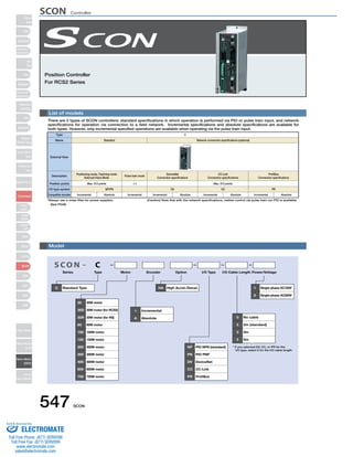
The document provides information about SCON controllers, including: - There are standard and network specifications, with incremental and absolute options. Only incremental is available for pulse train input. - It lists motor, encoder, I/O cable length, power/voltage options. Network connection specifications are also optional. - Control can be performed via PIO, pulse train, or connecting to a field network depending on the specification. Positioning of up to 512 points is possible in positioner or solenoid valve modes.

Empfohlen
Weitere ähnliche Inhalte
Was ist angesagt?
Was ist angesagt? (18)
Ähnlich wie Iai scon controller_specsheet
Ähnlich wie Iai scon controller_specsheet (20)
Mehr von Electromate
Mehr von Electromate (20)
Kürzlich hochgeladen
Kürzlich hochgeladen (20)
Iai scon controller_specsheet
- 1. SCON Controller Position Controller For RCS2 Series List of models There are 2 types of SCON controllers: standard specifications in which operation is performed via PIO or pulse train input, and network specifications for operation via connection to a field network. Incremental specifications and absolute specifications are available for both types. However, only incremental specified operations are available when operating via the pulse train input. S CON Series Type Motor Encoder Option I/O Type I/O Cable Length Power/Voltage C Standard Type 20 20W motor 30D 30W motor (for RCS2) 30R 30W motor (for RS) 60 60W motor 100 100W motor 150 150W motor 200 200W motor 300 300W motor 400 400W motor 600 600W motor 750 750W motor 547 SCON HA High Accel./Decel. 1 Single-phase AC100V I Incremental A Absolute NP PIO NPN (standard) PN PIO PNP DV DeviceNet CC CC-Link PR ProfiBus 2 Single-phase AC200V 0 No cable 2 2m (standard) 3 3m 5 5m C * If you selected DV, CC, or PR for the I/O type, select 0 for the I/O cable length. Type C Name Standard External View Description Positioning mode, Teaching mode Solenoid Valve Mode Position points I/O type symbol Compatible encoder Max. 512 points Incremental NP/PN Pulse train mode DeviceNet Connection specifications CC-Link Connection specifications ProfiBus Connection specifications (−) Network connection specifications (optional) Max. 512 points DV CC PR Model Absolute Incremental Incremental Absolute Incremental Absolute Incremental Absolute *Always use a noise filter for power supplies. (Caution) Note that with the network specifications, neither control via pulse train nor PIO is available. (See P548) Slider Type Mini Standard Controllers Integrated Rod Type Mini Standard Controllers Integrated Table/Arm /FlatType Mini Standard Gripper/ Rotary Type Linear Servo Type Cleanroom Type Splash-Proof Controllers PMEC /AMEC PSEP /ASEP ROBO NET ERC2 PCON ACON SCON PSEL ASEL SSEL XSEL Pulse Motor Servo Motor (24V) Servo Motor (200V) Linear Servo Motor Sold & Serviced By: ELECTROMATE Toll Free Phone (877) SERVO98 Toll Free Fax (877) SERV099 www.electromate.com sales@electromate.com
- 2. * Always use a noise filter when connecting power PC software (See P555) Teaching Pendant RS232 version <Model: RCM-101-MW> Horizontal 0 units ~100W Vertical ~100W ~400W ~750W 2.5 lead 1 unit 2 units Horizontal 1 unit ~400W ~750W 1.25 lead 0 units Vertical 1 unit 1 unit Actuator RCS2 series / single-axis robot / linear servo actuator ROBONET Gateway Unit + extension unit (See P505-506) DeviceNet compatible version <Model: RGW-DV> + <Model: REXT-CTL> CC-Link compatible version <Model: RGW-CC> + <Model: REXT-CTL> Pulse converter AK-04 (option) Description: Pulse converter (model: AK-04) + I/O e-CON connector Use this converter if output pulses from the host controller are of open collector specification. This converter is used to convert the open-collector command output pulses from the host controller to differential pulses. Converting open collector pulses to differential pulses improves noise resistance. Two phases of differential pulses equivalent to those from the line driver 26C31 are output. The e-CON connector is used as an input/output connector to simplify the field wiring. SCON 548 Basic Specifications ・Input power :DC24V±10% (Max. 50mA) ・Input pulse :Open collector (collector current Max. 12mA) ・Input frequency :200 kHz or less ・Output pulse :26C31 equivalent differential output (Max. 10mA) ・External dimensions :See the figure at right (cable connector not included) ・Weight :10g or less (cable connector not included) ・Accessories :I/O e-CON connector 3M 37104-3122-000FL Applicable wire: AWG No. 24 to 26, 0.14 to less than 0.3mm2 Outer diameter of finished wire 1.0 to 1.2mm I/O Flat Cable Model: CB-PAC-PIO020 Cable length Standard 2m (Supplied with the controller) For a replacement cable, see P556. Pulse train control plug + shell (Supplied with the controller) Pulse train control cable Model: CB-SC-PIOS (Optional) Motor Cable Model: CB-RCC-MA Standard 1m / 3m / 5m For a replacement cable, see P556. USB version Model: RCM-101-USB (See P555) Model: CON-PT-M Model: CON-T Model: RCM-E * The cable is supplied with the PC software Encoder Cable Model: CB-RCS2-PA Standard 1m / 3m / 5m For a replacement cable, see P556. PLC Main Power Supply Single-phase AC100V Single-phase AC200V Recommended: MC1210 (Manufacturer: TDK-Lambda) (Available through IAI. Please inquire for details.) Absolute data retention battery (see P555) Model: AB-5 (included with absolute type controller) Regenerative resistor unit (See P555) Model: REU-2 (Optional) Field Network ProfiBus compatible version Model: RGW-PR + Model: REXT-CTL Required Number of Regenerative Resistance Units Required Number of Units (RCS2-RA13R only) * Depending on the operating conditions, ޓmore regenerative resistor may be needed. * If the open collector method is used for the command pulse train, always use the AK-04 pulse converter (option). System configuration ( ) SCON Controller Slider Type Mini Standard Controllers Integrated Rod Type Mini Standard Controllers Integrated Table/Arm /FlatType Mini Standard Gripper/ Rotary Type Linear Servo Type Cleanroom Type Splash-Proof Controllers PMEC /AMEC PSEP /ASEP ROBO NET ERC2 PCON ACON SCON PSEL ASEL SSEL XSEL Pulse Motor Servo Motor (24V) Servo Motor (200V) Linear Servo Motor Sold Serviced By: ELECTROMATE Toll Free Phone (877) SERVO98 Toll Free Fax (877) SERV099 www.electromate.com sales@electromate.com
- 3. I/O Specifications ■ Input section External input specifications Item Input voltage Input current ON/OFF power supply Isolation method NPN Specifications NPN Specifications PNP Specifications PNP Specifications Explanation of I/O Signal Functions ■ Output section External output specifications SCON-C is compatible with all of the following control methods. Positioning is possible with up to 512 points in positioner mode and up to 7 points in solenoid valve mode. ■ Control Function by Type 549 SCON Specifications DC24V ±10% 4mA / 1 point ON voltage…Min DC18.0V (3.5mA) ON voltage…Max DC6.0V (1mA) Photocoupler +24V 0V Input 5.6kΩ Logic circuit Internal circuit Input Item Load Voltage Max. load current Leak current Isolation method Specifications DC24V 100mA / 1 point 400mA / 8 points Max 0.1mA / 1 point Photocoupler 10Ω Load Output Load Output Logic Internal circuit circuit +24V 0V Input Logic circuit Internal circuit Input 5.6kΩ 10Ω Output Output Load Load Logic Internal circuit circuit Type SCON-C Features Positioner mode ○ This is the basic operating mode, in which the user designates position numbers and inputs start signals. Teaching mode ○ In this mode, it is possible to move the slide (rod) via external signal, and then register the stop position as position data. Solenoid valve mode ○ The actuator can be moved simply by ON/OFF of position signals. This mode supports the same control signals you are already familiar with on solenoid valves of air cylinders. Pulse train mode ○ In this mode, you can operate the actuator freely using pulse trains without inputting position data. Network compatible ○ If the optional network specifications are selected, direct connection to a field network is possible. CAUTION Note that for network compatible types, PIO and pulse train communication are not available. SCON Controller Slider Type Mini Standard Controllers Integrated Rod Type Mini Standard Controllers Integrated Table/Arm /FlatType Mini Standard Gripper/ Rotary Type Linear Servo Type Cleanroom Type Splash-Proof Controllers PMEC /AMEC PSEP /ASEP ROBO NET ERC2 PCON ACON SCON PSEL ASEL SSEL XSEL Pulse Motor Servo Motor (24V) Servo Motor (200V) Linear Servo Motor Sold Serviced By: ELECTROMATE Toll Free Phone (877) SERVO98 Toll Free Fax (877) SERV099 www.electromate.com sales@electromate.com
- 4. RES Reset signal Turning this signal ON resets the alarms that are present. If this signal is turned ON while the actuator is paused (*STP is OFF), the remaining movement can be cancelled. SON Servo ON signal The servo remains on while this signal is ON, or off while the signal is OFF. HOME Home return signal Turning this signal ON preforms home-return operation. PWRT Teaching signal In the teaching mode, specify a desired position number and then turn this signal ON for at least MOVE Moving signal Turns ON while the actuator is moving (home return), including when there is push force. SCON 550 Explanation of I/O Signal Functions The table below explains the functions allocated to the controller’s I/O signal. Since the signals that can be used vary depending on the controller type and settings, check the signal table for each controller to confirm the available functions. ■ Signal Function Description Classification Signal abbreviations CSTR Start signal Signal Function description Input this signal to cause the actuator to start moving to the position set by the command position number signal. PC1 to PC256 Command position number signal This signal is used to input a target position number (binary input). BKRL Brake forced release signal This signal forcibly releases the brake. RMOD Running mode switching signal Operations mode can be switched when the controller’s MODE switch is set to AUTO. (AUTO if this signal is OFF, MANU if the signal is ON) * STP Pause signal Turning this signal OFF causes the moving actuator to decelerate to a stop. The actuator will resume the remaining movement if the signal is turned ON during the pause. MODE Teaching mode signal Turning this signal ON switches the controller to the teaching mode (provided that CSTR, JOG+ and JOG- are all OFF and the actuator is not moving) JISL JOG+, JOG− JOG/INCHING switching signal JOG signal When the main signal is off, the JOG operation will be conducted for JOG+ and JOG-. When the signal is on, the unit will do the inching operation for JOG+ and JOG-. When the JISL signal is OFF and the JOG +/- signal turns ON, the unit will jog in the + (positive) direction when the JOG + turns on and the - (negative) direction when the JOG - turns on. During the JOG operation, the unit slows to a stop when the JOG +/- signal turns off. 20ms to write the current position to the specified position number. ST0 to ST6 Start position command signal Turning this signal ON in the solenoid valve mode causes the actuator to move to the specified position. (Start signal is not required) TL Torque limit selection signal While this signal is ON, torque is limited by the value set by a parameter. The TLM signal turns on if torque has reached the specified value. CSTP Forced Stop Signal Servo OFF is performed when this signal is ON for more than 10ms. DCLR Deviation counter clear signal When this signal is ON, the position deviation counter is cleared continuously. PEND/INP In position signal This signal turns ON when the actuator has entered the positioning band after movement. If the actuator has exceeded the positioning band, PEND does not turn OFF, but INP does. PEND and INP can be swapped using a parameter. Input Output PM1 to PM256 Positioning complete signal This signal is used to output the position number achieved at completion of positioning (binary output) HEND Home return completion signal This signal turns ON upon completion of home return. ZONE1 Zone signal Turns ON if the actuator’s current position is within the range set by the parameter. PZONE Position zone signal This signal turns ON when the current actuator position has entered the range specified by position data during position movement. PZONE can be used together with ZONE1, but PZONE is valid only during movement to a specified position. RMDS Running mode status signal This outputs the operation mode status. * ALM Controller alarm status signal Turns ON when the controller is in normal condition, and turns OFF when an alarm occurs. SV Servo ON status signal This signal turns ON when servo is ON. * Emergency stop status signal This signal remains ON while the controller is not in the emergency stop mode, and turns OFF EMGS once an emergency stop has been actuated. * BALM Absolute battery voltage drop warning signal With the absolute specifications for the controller, turns OFF when the absolute battery voltage drops. MODES Mode status signal The mode signal input turns it ON when it goes into teaching mode. It turns OFF when it goes into normal mode. WEND Writing complete signal This signal remains OFF after the controller has switched to the teaching mode. It turns ON upon completion of data write using the PWRT signal. If the PWRT signal is turned Off, this signal also turns OFF. PE0 to PE6 Current position number signal This signal turns ON after the controller has completed moving to the target position in the solenoid valve mode. PWR System Ready Signal Turns ON when it starts up normally after turning ON the controller. (Dedicated pulse train type) TLR Torque limiting signal This signal turns ON once the motor torque has reached the specified value in a condition where torque is being limited by the TL signal. (Dedicated pulse train mode) ALM1 to ALM8 Alarm Code Output Signal During a controller alarm, the alarm details are output in code. (Dedicated pulse train mode) LSO to LS2 Limit switch output signal Each signal turns ON when the current actuator position has entered the positioning band before or after the target position. If the actuator has already completed home return, these signals are output even before a movement command is issued or while the servo is OFF. (Note) Signals with asterisks (*) are normally ON and OFF during operation. SCON Controller Slider Type Mini Standard Controllers Integrated Rod Type Mini Standard Controllers Integrated Table/Arm /FlatType Mini Standard Gripper/ Rotary Type Linear Servo Type Cleanroom Type Splash-Proof Controllers PMEC /AMEC PSEP /ASEP ROBO NET ERC2 PCON ACON SCON PSEL ASEL SSEL XSEL Pulse Motor Servo Motor (24V) Servo Motor (200V) Linear Servo Motor Sold Serviced By: ELECTROMATE Toll Free Phone (877) SERVO98 Toll Free Fax (877) SERV099 www.electromate.com sales@electromate.com
- 5. SCON Controller Positioning mode / teaching mode / solenoid valve mode Pulse train mode (differential output) PIO connector (NPN) Pin Number Classification Signal 1A 24V Power Supply Input Output Power Supply 2A 3A 4A 5A 6A 7A 8A 9A 10A 11A 12A 13A 14A 15A 16A 17A 18A 19A 20A 1B 2B 3B 4B 5B 6B 7B 8B 9B 10B 11B 12B 13B 14B 15B 16B 17B 18B 19B 20B 24V Not used Not used IN0 IN1 IN2 IN3 IN4 IN5 IN6 IN7 IN8 IN9 IN10 IN11 IN12 IN13 IN14 IN15 OUT0 OUT1 OUT2 OUT3 OUT4 OUT5 OUT6 OUT7 OUT8 OUT9 OUT10 OUT11 OUT12 OUT13 OUT14 OUT15 Not used Not used 0V 0V * Connect 24V between pins 1A and 2A, and 0V between pins 19B and 20B. 24V 551 SCON DC24V±10% 1 Not used Shield PIO connector (NPN) 1A 24V DC24V±10% PULSE connector Pin Number Classification Signal Pin Number Classification Signal Twist pair Shield Input Output Ground Power Supply Input Output Power Supply Classification Parameter Selections (PIO Patterns) Pulse Train Mode 0 1 2 3 4 5 0 Positioning Mode Teaching Mode 256-point Mode 512-point Mode Solenoid Valve Mode 1 Solenoid Valve Mode 2 Pulse Train Mode P24 Number of Positions Zone Signal P-zone Signal 64 points 64 points 256 points 512 points 7 points 3 points P24 IN0 PC1 PC1 PC1 PC1 ST0 ST0 * The names of signals above, the values enclosed in ( ) are functions before homing is performed. * The signals with an asterisk are normally ON, and OFF during operation. 23456789 10 11 12 13 14 Shell Not used PP /PP NP /NP AFB /AFB BFB /BFB ZFB /ZFB GND GND Shield 2A 3A 4A 5A 6A 7A 8A 9A 10A 11A 12A 13A~20A 1B 2B 3B 4B 5B 6B 7B 8B 9B 10B 11B 12B 13B 14B 15B 16B 17B~18B 19B 20B 24V Not used Not used SON RES HOME TL CSTP DCLR BKRL RMOD Not used PWR SV INP HEND TLR *ALM *EMGS RMDS ALM1 ALM2 ALM4 ALM8 ZONE1 ZONE2 Not used 0V 0V * The shield on the twisted pair cable connected to the pulse connector must be connected to the shell. Also, the cable length must not be longer than 10m. * Connect 24V between pins 1A and 2A, and 0V between pins 19B and 20B. Pin Number 1A 2A 3A 4A 5A 6A 7A 8A 9A 10A 11A 12A 13A 14A 15A 16A 17A 18A 19A 20A 1B 2B 3B 4B 5B 6B 7B 8B 9B 10B 11B 12B 13B 14B 15B 16B 17B 18B 19B 20B 24V Input Output 0V 0V IN1 IN2 IN3 IN4 IN5 IN6 IN7 IN8 IN9 IN10 IN11 IN12 IN13 IN14 IN15 OUT0 OUT1 OUT2 OUT3 OUT4 OUT5 OUT6 OUT7 OUT8 OUT9 OUT10 OUT11 OUT12 OUT13 OUT14 OUT15 PC2 PC4 PC8 PC16 PC32 BKRL RMOD HOME * STP CSTR RES SON PM1 PM2 PM4 PM8 PM16 PM32 MOVE ZONE1 PZONE RMDS HEND PEND SV * EMGS * ALM * BALM PC2 PC4 PC8 PC16 PC32 MODE JISL JOG+ JOG− RMOD HOME * STP CSTR/PWRT RES SON PM1 PM2 PM4 PM8 PM16 PM32 MOVE MODES PZONE RMDS HEND PEND/WEND SV * EMGS * ALM * BALM PC2 PC4 PC8 PC16 PC32 PC64 PC128 − BKRL RMOD HOME * STP CSTR RES SON PM1 PM2 PM4 PM8 PM16 PM32 PM64 PM128 PZONE RMDS HEND PEND SV * EMGS * ALM * BALM PC2 PC4 PC8 PC16 PC32 PC64 PC128 PC256 BKRL RMOD HOME * STP CSTR RES SON PM1 PM2 PM4 PM8 PM16 PM32 PM64 PM128 PM256 RMDS HEND PEND SV * EMGS * ALM * BALM ST1 ST2 ST3 ST4 ST5 ST6 BKRL RMOD HOME * STP RES SON PE0 PE1 PE2 PE3 PE4 PE5 PE6 ZONE1 PZONE RMDS HEND PEND SV * EMGS * ALM * BALM ST1 (JOG+) ST2 (-) BKRL RMOD RES SON LSO LS1 (TRQS) LS2 ZONE1 PZONE RMDS HEND SV * EMGS * ALM * BALM P24 NC NC P24 NC NC SON RES HOME TL CSTP DCLR BKRL RMOD PWR SV INP HEND TLR * ALM * EMGS RMDS ALM1 ALM2 ALM4 ALM8 ZONE1 ZONE2 N N N N I/O wiring drawing I/O Signal Table *Choose from 7 types of signal allocation. Slider Type Mini Standard Controllers Integrated Rod Type Mini Standard Controllers Integrated Table/Arm /FlatType Mini Standard Gripper/ Rotary Type Linear Servo Type Cleanroom Type Splash-Proof Controllers PMEC /AMEC PSEP /ASEP ROBO NET ERC2 PCON ACON SCON PSEL ASEL SSEL XSEL Pulse Motor Servo Motor (24V) Servo Motor (200V) Linear Servo Motor Sold Serviced By: ELECTROMATE Toll Free Phone (877) SERVO98 Toll Free Fax (877) SERV099 www.electromate.com sales@electromate.com
- 6. Command Pulse Train Shapes Input terminals Forward Reverse Reverse pulse train The forward pulse train controls the amount of forward motor rotation; the reverse pulse train controls the same in reverse direction. Low Sign The command pulse controls the amount of motor rotation, and the command sign controls the direction of rotation. A (frequency-quadrupled) A/B phase pulse with a 90° phase difference is used to control the amount and direction of rotation. SCON 552 Input Section Output Section : Line-driver interface: 500kpps Open collector interface: 200kpps (AK-04 required) : Photocoupler Max. No. of Input Pulses Isolation method Output method : Line-driver output Isolation : Not isolated 26C31 or equivalent 3. PP 4. /PP 180Ω Internal circuit 5. NP 6. /NP 180Ω Internal circuit SCON 26C32 or equivalent 7. AFB SCON 8. /AFB Internal circuit 9. BFB 10. /BFB Internal circuit 11. ZFB 12. /ZFB 13. GND 14. GND Internal circuit GND GND Pulse converter AK-04 (+DC24V) N24 (0V) Upper-level controller P24 N24(0V) SCON 1ޓ24V 2ޓGND 3ޓPP 4ޓNP 3 4 5 ޓNP 6 ޓPP /PP /NP PPޓ1 /PPޓ2 NPޓ3 /NPޓ4 * Use the DC24V power supply connected to AK-04 to also supply power to the PIO interface. * Make sure the cable between the pulse output unit (PLC) and AK-04 is as short as possible. Also, the cable between AK-04 and the pulse connector should be 2m or shorter. Forward pulse train Pulse train Forward pulse train PP, /PP PP, /PP PP, /PP PP, /PP High High Low A/B phase pulse train Reverse pulse train Pulse train Sign A/B phase pulse train NP, /NP NP, /NP NP, /NP NP, /NP PP, /PP NP, /NP PP, /PP NP, /NP Positive Logic Negative Logic Pulse Train Type I/O Specifications (differential line driver specifications) Pulse Train Ttype I/O Specifications (open collector specifications) Command Pulse Input State SCON Controller Slider Type Mini Standard Controllers Integrated Rod Type Mini Standard Controllers Integrated Table/Arm /FlatType Mini Standard Gripper/ Rotary Type Linear Servo Type Cleanroom Type Splash-Proof Controllers PMEC /AMEC PSEP /ASEP ROBO NET ERC2 PCON ACON SCON PSEL ASEL SSEL XSEL Pulse Motor Servo Motor (24V) Servo Motor (200V) Linear Servo Motor Sold Serviced By: ELECTROMATE Toll Free Phone (877) SERVO98 Toll Free Fax (877) SERV099 www.electromate.com sales@electromate.com
- 7. SCON Controller Table of specifications Item Specifications 553 SCON RCS2 series actuator / single axis robot / linear servo actuator 1-axis Positioner type / pulse train type EEPROM 40 pin connector 16 input points / 16 output points External supply DC24V±10% RS485 1ch Device Net, CC-Link, ProfiBus CB-PAC-PIO □□□ Motor Capacity Connected actuator Number of control axes Operating method Positioning Points Backup memory I/O connector Number of I/O I/O power Serial Communication Field Network Peripheral device communication cable Command pulse train input method Max. input pulse frequency Position detection method Emergency stop function Electromagnetic brake forced release Input Voltage Power Supply Capacity Dielectric strength voltage Vibration resistance Ambient operating temperature Ambient operating humidity Ambient operating atmosphere Protection class Weight External dimension Less than 400W 400W or more 512 points Differential line driver method / open collector method (converted to differential with the pulse converter *1) Differential line driver method: up to 500 kpps / open collector method (using pulse converter): up to 200kpps Incremental encoder / Absolute encoder Y (integrated relay) Brake release switch ON/OFF Single-phase AC90V to AC126.5V Single-phase AC180V to AC253V Single-phase AC180V to AC253V 20W/ 74VA 30W/ 94VA 60W/ 186VA 100W/ 282VA 150W/ 376VA 200W/ 469VA 400W/ 844VA 600W/ 1212VA 750W/ 1569VA DC500V 100MΩ or more XYZ directions 10 to 57Hz, One side amplitude: 0.035mm (continuous), 0.075mm (intermittent) 58 to 150 Hz 4.9 m/s2 (continuous), 9.8 m/s2 (intermittent) 0~40ºC 10 - 95% (non-condensing) Without corrosive gases IP20 Approximately 800g (plus 25g for the absolute specifications) 58mm (W)×194mm (H)×121mm (D) Approximately 1.1kg (plus 25g for absolute specifications) 72mm(W)×194mm (H)×121mm (D) (Note 1) For the command-pulse input method, use the differential line driver method offering higher noise resistance. If the open collector method must be used, convert the pulse to differential using the optional pulse converter (AK-04). Slider Type Mini Standard Controllers Integrated Rod Type Mini Standard Controllers Integrated Table/Arm /FlatType Mini Standard Gripper/ Rotary Type Linear Servo Type Cleanroom Type Splash-Proof Controllers PMEC /AMEC PSEP /ASEP ROBO NET ERC2 PCON ACON SCON PSEL ASEL SSEL XSEL Pulse Motor Servo Motor (24V) Servo Motor (200V) Linear Servo Motor Sold Serviced By: ELECTROMATE Toll Free Phone (877) SERVO98 Toll Free Fax (877) SERV099 www.electromate.com sales@electromate.com
- 8. Operating mode switch 9 10 11 Name Explanation *The emergency stop switch on the teaching pendant becomes effective when the line is connected, regardless of whether this switch is set to AUTO or MANU. Take note that an emergency stop will be actuated momentarily when the teaching-pendant or SIO communicat ion cable is disconnected. This is a normal phenomenon and does not indicate an error. SCON 554 External dimensions Less than 400W 58 4.2 194 (200.5) 5 184 ø4.2 29 (80) 121 With the absolute battery installed Name of Each Part 400W or more 72 4.2 194 (200.5) 5 184 ø4.2 (80) 43 121 With the absolute battery installed LED display These LED colors indicate the condition of the controller. Name Color Explanation PWR SV ALM EMG Green Green Orange Red Lit when the system is ready (after power is ON, CPU normal functions) Lit when servo is ON Lit during an alarm Lit during an emergency stop Rotary switch This is the address setting switch for identifying each controller when they are linked. Piano switch Controller system switch. Operating mode switch OFF: positioner mode ON: pulse train control mode *Enabled at power ON. Remote update switch (normally set to OFF) OFF: normal operating mode ON: update mode *Enabled when power is ON or during soft reset. System I/O connector 1 2 Connector for the emergency stop switch etc. Regeneration unit connector Connector for resistance unit that absorbs regeneration current produced when the actuator decelerates to a stop. Motor connector (X-SEL, ECON, RCS compatible) Actuator motor cable connector. Power supply connector AC power connector. Divided into the control power input and motor power input. Grounding screw Protective grounding screw. Always ground this screw. Pulse train control connector This connector is used during pulse train control mode operations. It is disconnected during operations in positioner mode. PIO connector Connector for the cable for parallel communications with the PLC and other peripheral devices. SIO connector 12 Connector for the teaching pendant or PC communications cable. Brake release switch 13 This is the electromagnetic brake forced release switch, integrated with the actuator. *It is necessary to connect the DC 24V power for the brake drive. Brake power connector 14 Brake power DC 24V supply connector (only required when the brake equipped actuator is connected) Encoder sensor connector (X-SEL-P/Q compatible) 15 Encoder sensor cable connector Absolute battery connector 16 Connector for the absolute data backup battery. (Required only for absolute encoder specifications) Absolute battery holder Battery holder for installing the absolute data backup battery Name Explanation MANU AUTO Do not receive PIO commands Accept PIO commands 9 10 11 12 13 17 1 2 3 4 5 6 7 8 14 15 16 1 2 3 4 5 6 7 8 17 SCON Controller Slider Type Mini Standard Controllers Integrated Rod Type Mini Standard Controllers Integrated Table/Arm /FlatType Mini Standard Gripper/ Rotary Type Linear Servo Type Cleanroom Type Splash-Proof Controllers PMEC /AMEC PSEP /ASEP ROBO NET ERC2 PCON ACON SCON PSEL ASEL SSEL XSEL Pulse Motor Servo Motor (24V) Servo Motor (200V) Linear Servo Motor Sold Serviced By: ELECTROMATE Toll Free Phone (877) SERVO98 Toll Free Fax (877) SERV099 www.electromate.com sales@electromate.com
- 9. Teaching Pendant This is a teaching device that provides information on functions such as position input, test runs, and monitoring. CON-PT-M-ENG (Touch panel CON-T-ENG (Standard type) Features Model Note: The version of RCM-E-ENG that can be used with ROBONET is 2.08 or later. PC Software (Windows Only) (113.5) 110.0 66.6 39.0 Item CON-PT-M-ENG CON-T-ENG RCM-E-ENG Temp: 0~40ºC; Humidity: 85% RH or below No corrosive gases. Especially no dust. IP40 IP54 Approx. 750g A startup support software for inputting positions, performing test runs, and monitoring. With enhancements for adjustment functions, the startup time is shortened. RCM-101-MW (External device communications cable + RS232 conversion unit) ■ Regenerative Resistance Unit ■ Battery for retaining absolute data Horizontal Vertical 555 SCON 0.3m 5m External device communications cable CB-RCA-SIO050 PC Software (CD) RS232 adapter RCB-CV-MW RCM-101-USB (External device communications cable + USB adapter + USB cable) USB adapter RCB-CV-USB 3m 5m PC Software (CD) External device communications cable CB-RCA-SIO050 USB cable CB-SEL-USB030 teaching pendant) RCM-E-ENG (Simple teaching pendant) Features Model Configuration Model Configuration Specifications Display 3-color LED touch panel with backlight Approx. 400g 5m 20 char × 4 lines LCD .display Approx. 400g 16 char. × 2 lines LCD display 5m CON-PT-M-ENG CON-T-ENG RCM-E-ENG 21 15.1 26.2 6.3 23.5 43 148.5 7 72.5 (34) 46.9 218.3 89.6 CON-T Options • Wall-mounting hook Model HK-1 • Strap Model STR-1 132 92.1 180 Configuration Data input Actuator motion Ambient operating temp/humidity Ambient operating atmosphere Protection class Weight Cable length Option A unit that returns the regenerative current, generated during the acceleration/deceleration of the motor, into heat. In the tables below, check the total power output of the actuator to see if a regenerative resistor is needed. REU-2 (for SCON/SSEL) Features Model Specifications Actuator weight Actuator-Controller 0.9kg 220Ωޓ80W CB-SC-REU010 (for SSEL) Required Number of Units Required Number of Units (RCS2-RA13R only) 0 units ~100W ~100W 2.5 lead 1.25 lead * Depending on the operating conditions, ޓmore regenerative resistor may be needed. * Depending on the operating conditions, ޓmore regenerative resistor may be needed. Exterior Dimensions ø5 175 16.6 126 34 5 195 186 Horizontal 1 unit 0 units 1 unit 2 units ~400W ~750W ~400W ~750W Vertical 1 unit 1 unit * If two regenerative units are needed, acquire one REU-2 and one REU-1 (See P596). Internal regenerative resistance Connection Cable (included) Battery for saving absolute data, when operating an actuator with an absolute encoder. AB-5 Features Model SCON Controller Slider Type Mini Standard Controllers Integrated Rod Type Mini Standard Controllers Integrated Table/Arm /FlatType Mini Standard Gripper/ Rotary Type Linear Servo Type Cleanroom Type Splash-Proof Controllers PMEC /AMEC PSEP /ASEP ROBO NET ERC2 PCON ACON SCON PSEL ASEL SSEL XSEL Pulse Motor Servo Motor (24V) Servo Motor (200V) Linear Servo Motor Sold Serviced By: ELECTROMATE Toll Free Phone (877) SERVO98 Toll Free Fax (877) SERV099 www.electromate.com sales@electromate.com
- 10. When you need spare parts after purchasing the product, such as when replacing a cable, refer to the list of models below. Note 1 Signal Color Wire Pink Purple White Blue/red Orange/White Green/White AWG26 Ground Blue Black Yellow Green Brown Pin No. 5 4 2 1 3 6 9 8 7 10 11 12 13 14 A A B Z B Z LS+ FG SD SD BAT− VCC GND LS-BAT+ Pin No. Signal Color Wire 0V LS CREEP OT RSV Pin No. Signal Color Wire Wire Pin No. 0. 2sq soldered 9 8 7 6 5 4 3 12 10 11 12 13 14 Color Black White/Black Red White/Red Green White/Green Yellow White/Yellow Brown White/Brown Blue White/Blue Gray White/Gray Signal Not used Not used PP /PP NP /NP AFB /AFB BFB /BFB ZFB /ZFB GND GND AWG26 AWG26 SCON 556 Spare parts L Pin No. Signal Color Wire Shield Pin No. 10 11 12 13 26 25 24 23 9 18 19 5 4 2 1 3 6 8 7 14 15 16 17 20 Signal E24V 0V LS CREEP OT RSV A+ A− B+ B− Z+ Z− SRD-SRD+ BAT+ BAT− VCC BKR-GND E24V Black White/Black Red White/Red Green White/Green Yellow White/Yellow Brown White/Brown Blue White/Blue Gray White/Gray Shield The shield is connected to a cable clamp. Motor cable/Motor robot cable (Front view) (Front view) Encoder cable/Encoder robot cable (41) (14) Encoder cable/Encoder robot cable for RCS2-RT6/RT6R/RT7/RA13R I/O Flat Cable SCON Pulse Train Control Cable Model CB-SC-PIOS □□□ L 10 10 1 Plug: 10114-3000PE (Sumitomo 3M) Shell: 10314-52F0-008 (Sumitomo 3M) No connector (ø9) * Enter the cable length (L) into □□□ . Compatible to a maximum of 10 meters. Ex.: 080 = 8 m Model CB-RCC-MA □□□ / CB-RCC-MA □□□ -RB * Enter the cable length (L) into □□□ . Compatible to a maximum of 30 meters. Ex.: 080 = 8 m L 4 1 1 4 Wire Color Signal Pin No. Pin No. 0.75sq Green PE 1 Signal Color Wire 0.75sq (crimped) 1 U Red (20) (10) Controller side Mechanical side (16) (ø9) (21) (18) (41) U V W Red White Black 2 3 4 2 3 4 V W PE White Black Green Model CB-RCS2-PA □□□ / CB-X3-PA □□□ * Enter the cable length (L) into □□□ . Compatible to a maximum of 30 meters. Ex.: 080 = 8 m 1 9 1 13 14 26 18 L Ground wire and braided shield Note 2 Note 4 Gray Red (crimped) Orange 15 16 17 18 BK− BK+ Wire Gray/White Brown/White Pink Purple White Blue/red Orange/White Green/White Blue Orange Black Yellow Green The shield is connected to the hood by a clamp. Note 3 AWG26 (soldered) 21 22 BKR+ Brown/White Gray/White Color Brown Gray Red (ø10) (13) (37) (15) (25) (Front view) Controller side Mechanical side (Front view) Model CB-RCS2-PLA □□□ / CB-X2-PLA □□□ * Enter the cable length (L) into □□□ . Compatible to a maximum of 30 meters. Ex.: 080 = 8 m 1 9 1 13 14 26 18 L 6 (ø10) Ground wire and braided shield (crimped) AWG26 (soldered) White/Orange White/Green Brown/Blue Brown/Yellow Brown/Red Brown/Black White/Blue A+ 10 1 A White/Blue Wire Color Signal Pin No. Pin No. Signal Color Wire The shield is connected to the hood by a clamp. (The wire color White/Blue indicates the colors of the band and insulation.) (crimped) 1 E24V White/Orange White/Yellow White/Red White/Black White/Purple White/Gray Orange Green Purple Gray Red Black Blue Yellow 0V LS CREEP OT RSV A− B+ B− Z+ Z− SRD+ SRD− BAT+ BAT− VCC GND BKR− BKR+ 11 12 13 26 25 24 23 9 18 19 12345678 14 15 16 17 20 21 22 LS side (13) (41) (14) (37) (8) (15) (18) (25) 23456 23456789 10 11 12 13 14 15 16 17 18 ABBZZ FG SD SD BAT+ BAT− VCC GND BK− BK+ White/Green Brown/Blue Brown/Yellow Brown/Red Brown/Black White/Yellow White/Red White/Black White/Purple White/Gray Ground Orange Green Purple Gray Red Black Blue Yellow (Front view) Controller side Mechanical side B Flat cable A (crimped) Flat cable B (crimped) AWG28 Half-pitch MIL socket: HIF6-40D-1. 27R (Hirose) Flat cable (20-core) × 2 HIF6-40D-1. 27R 20A 20B 1A 1B A No connector No connector Brown-1 24V Brown-3 1A OUT0 2A 24V Red-1 3A Orange-1 4A Yellow-1 5A IN0 Green-1 6A IN1 Blue-1 7A IN2 Purple-1 8A IN3 Gray-1 9A IN4 White-1 10A IN5 Black-1 11A IN6 Brown-2 12A IN7 Red-2 13A IN8 Orange-2 14A IN9 Yellow-2 15A IN10 Green-2 16A IN11 Blue-2 17A IN12 Purple-2 18A IN13 Gray-2 19A IN14 White-2 20A IN15 Black-2 1B 2B 3B 4B 5B 6B 7B 8B 9B 10B 11B 12B 13B 14B 15B 16B 17B 18B 19B 20B OUT1 OUT2 OUT3 OUT4 OUT5 OUT6 OUT7 OUT8 OUT9 OUT10 OUT11 OUT12 OUT13 OUT14 OUT15 0V 0V Red-3 Orange-3 Yellow-3 Green-3 Blue-3 Purple-3 Gray-3 White-3 Black-3 Brown-4 Red-4 Orange-4 Yellow-4 Green-4 Blue-4 Purple-4 Gray-4 White-4 Black-4 Model CB-PAC-PIO □□□ * Enter the cable length (L) into □□□ . Compatible to a maximum of 10 meters. Ex.: 080 = 8 m Min. bend radius r = 50 mm or larger (when movable type is used) * Only robot cable is to be used in a cable track. Min. bend radius r = 50 mm or larger (when movable type is used) * Only the robot cable is to be used in a cable track. Min. bend radius r = 50 mm or larger (when movable type is used) *Only the robot cable is to be used in a cable track. SCON Controller Slider Type Mini Standard Controllers Integrated Rod Type Mini Standard Controllers Integrated Table/Arm /FlatType Mini Standard Gripper/ Rotary Type Linear Servo Type Cleanroom Type Splash-Proof Controllers PMEC /AMEC PSEP /ASEP ROBO NET ERC2 PCON ACON SCON PSEL ASEL SSEL XSEL Pulse Motor Servo Motor (24V) Servo Motor (200V) Linear Servo Motor Sold Serviced By: ELECTROMATE Toll Free Phone (877) SERVO98 Toll Free Fax (877) SERV099 www.electromate.com sales@electromate.com