
Empfohlen
Weitere ähnliche Inhalte
Ähnlich wie Unique Solutions for Engineering Education
Ähnlich wie Unique Solutions for Engineering Education (20)
Kürzlich hochgeladen
Kürzlich hochgeladen (20)
Unique Solutions for Engineering Education
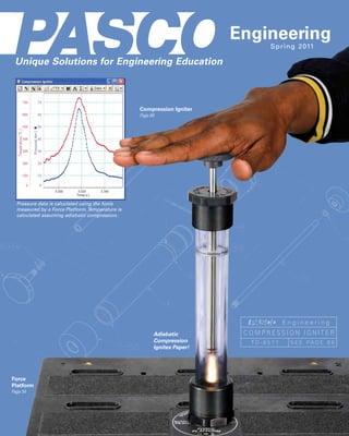
- 1. ®® Engineering S p r i n g 2 011 Unique Solutions for Engineering Education Compression Igniter Page 68 Pressure data is calculated using the force measured by a Force Platform. Temperature is calculated assuming adiabatic compression. Engineering Adiabatic COMPRESSION IGNITER Compression TD-8577 S E E PAG E 6 8 Ignites Paper! Force Platform Page 54
- 2. New Products Density Circulation Model Bicycle ME-6816 Gyroscope See page 88 ME-6837 Allows students to model, measure Rotating and understand the complex density driven circulation associated with heat Chair transfer through convection. ME-6856 See page 42 New Design features precision ball bearings that result in extremely low-friction for both the Bicycle Gyroscope Blue— and the Rotating Chair. Hotwater Clear— Bicycle Gyroscope Coolwater Mass Set Black— ME-6972 Icecoldwater See page 42 Modelofsmokerisingbeneathaninversionlayer.Therising plumeiscausedbyaheatingresistor(notincluded)placedat thebottomofthetank. MR 200 Digital/Analog Breadboard SE-9982 MR 100 Analog Breadboard See page 100 SE-9981 See page 100 Reinventing Edison: Reinventing Morse: Build Your Own Build Your Own Telegraph Light Bulb SE-7146 See page 98 SE-7145 See page 98 www.pasco.com/engineering
- 3. New Products – Table of Contents Large Structures Set DATA ACQUISITION ................................... 2-7 Computer Interfaces and Sensors .......2-5 ME-7003 See page 18 Graphing Datalogger .....................................6-7 STRUCTURES SYSTEM ....................... 8-20 Baltimore Truss Bridge MATERIALS ........................................................... 21 3 m long STATICS .............................................................22-25 MECHANICS .................................................26-55 Carts and Tracks ........................................ 26-31 Build this bridge and Projectile Motion ....................................... 32-33 15 other HUGE structures with Springs and Resonance ........................ 34-39 this one comprehensive set! Rotation ............................................................ 40-43 Energy ............................................................... 44-51 Human Body Mechanics ...................... 52-55 Destructible Bridge BIOLOGY ...........................................................56-60 Members ENVIRONMENTAL..................................61-65 ME-7004 See page 13 CHEMICAL ENGINEERING ...........66-67 THERMAL .........................................................68-83 Metal Plate Gas Laws......................................................... 68-69 Temperature Sensors ............................. 70-71 Heat Conduction ........................................ 72-73 Equivalent of Heat ..................................... 74-75 Thermal Expansion ................................... 76-77 Breakable Link Thermoelectric ............................................ 78-79 A broken link can be easily Investigate structural Thermal Radiation ............................................ 80 replaced with a new one by failure by inserting these simply sliding it onto the posts. breakable links into your Heat Engines................................................. 81-83 structures. FLUIDS.................................................................84-89 Bernoulli .......................................................... 84-85 CI Load Cell Amplifier Atmospheric Properties Atmospheric Pressure .................................. 86 CI-6464 Chamber ME-6813 Density .............................................................. 87-89 See page 9 See page 69 CIRCUITS .......................................................90-101 Electromagnetism ..................................... 90-93 Coils ........................................................................... 94 Electric Field Mapping .................................. 95 Dual Humidity/Temp/Dew Point Electrostatics ...................................................... 96 PS-2156 Resistance ............................................................ 97 See page 62 Circuits............................................................ 98-101 OPTICS ......................................................... 102-105 Optics Bench ..................................................... 102 Adjustable Focal Lenses .................................................................... 103 Length Lens Human Eye Model .......................................... 104 OS-8494 Diffraction ............................................................ 105 See pages 103, 104 LAB SUPPLIES .................................... 106-109 Mechanical Supplies ......................... 106-107 Rods and Clamps .................................. 108-109 Index .............................................................. 110-112 Contact Information .... Inside back cover www.pasco.com/engineering 1
- 4. Data Acquisition—ScienceWorkshop® PASCO’s Most Powerful Interface Uses PASCO’s ScienceWorkshop 750 ® DataStudio® Software Computer Interface - USB (See page 4) CI-7650 P Fast: 250,000 Hz P Built-in function generator P Built-in DC power supply (300 mA, ±5 V) P Accessory Power Amplifier (CI-6552A) increases power to 1 A, ±10 V P DataStudio Lite included P NI LabVIEW™ compatible Order Information: 750 Interface - USB .......................................................... CI-7650 (USB-compatible computers) DataStudio Software Site License ....................... CI-6871G AC/DC Circuit Board Power Amplifier (not shown) ................................... CI-6552A (See page 101) Over 45 ScienceWorkshop Sensors Available P Analog sensors P Signal conditioning built-in For sensor specifications, visit CI Load Cell Amplifier P Sturdy cases for easy www.pasco.com/engineering/data-acquisition CI-6464 mounting Acceleration CI-6558 Light, UVA CI-9784 Barometer CI-6531A Magnetic Field CI-6520A Carbon Dioxide CI-6561 Motion Sensor II CI-6742A Charge CI-6555 Oxygen Gas CI-6562 This amplifier allows users of the 500 CI Load Cell Amplifier NEW CI-6464 pH CI-6507A and 750 ScienceWorkshop Interfaces to collect data using the Structures System Colorimeter CI-6747 Photogate, Accessory ME-9204B 100N and 5N Load Cells. This system has Conductivity CI-6729 Photogate Head ME-9498A been successfully used at sample rates Current CI-6556 Photogate/Pulley System ME-6838A up to 10,000 Hz. The sample rate limit is determined by the interface and Current, High CI-6740 Pressure Sensor— Absolute CI-6532A computer used. Dissolved Oxygen CI-6542 Pressure Sensor—Low CI-6534A A separate amplifier is required for Drop Counter CI-6499 Respiration Rate CI-6535 each load cell. EKG CI-6539A Rotary Motion CI-6538 See page 9 for more information. Flow Rate CI-6730A Sound CI-6506B Order Information: Force CI-6537 Temperature CI-6605A CI Load Cell Amplifier* ...............CI-6464 Force, Economy CI-6746 Temperature, High Accuracy CI-6525 Required for Use: Force Platform CI-6461 Temperature, High, ScienceWorkshop Interface Freefall Adapter ME-9207B Type K Probe CI-6536 Load Cell 100N* .................................PS-2200 G-M Tube SN-7927A Temperature with Type K Probe CI-6526 Load Cell 5N*.......................................PS-2201 Heart Rate CI-6543B *Patents pending Thermistor Temperature CI-6527A Humidity, Relative CI-6559 Thermocline CI-6731 Ion Probes Time-of-Flight Accessory ME-6810 Ion-Selective Electrode Amplifier Box CI-6738 Voltage CI-6503 Laser Switch ME-9259A Light CI-6504A Motion Sensor II Light, Broad Spectrum CI-6630 (CI-6742A) Photogate/Pulley Light, High-Sensitivity CI-6604 System Light, Infrared CI-6628 Rotary Motion (CI-6538) (ME-6838) 2 www.pasco.com/engineering
- 5. Data Acquisition—ScienceWorkshop® Use ScienceWorkshop Use ScienceWorkshop sensors in your own Sensors with NI ELVIS™ circuits without a computer interface and LabVIEW™ CI Sensor Voltage Monitor NI ELVIS™ Adapters for CI-6611 PASCO Sensors P Take advantage of PASCO’s numerous fine quality sensors already mounted in a case and ready to use To collect data, plug an Analog or Digital Adapter into the prototyping board and Plug up to five ScienceWorkshop sensors at insert a sensor. Connect the adapter to a time into the front of the CI Sensor Voltage the appropriate I/O ports on ELVIS and the Monitor. The sensors’ output voltages are system is ready to use. accessed at the buss on the back of the Once data has been collected, students can CI Sensor Voltage Monitor. use the power and flexibility of LabVIEW software to display and condition the data as needed. This system provides the perfect opportunity for students to learn Back about digital and analog data processing techniques. Force Sensor Fan Accessory (See page 2) (See page 30) Front Force Sensor Voltage reading is proportional to the 1 kg force applied mass Sensor plugs into Force Accessory Dynamics System CI Sensor Voltage Bracket (See page 27) Monitor The NI ELVIS and LabVIEW software are used to control the Fan Accessory based on measurements from the Force Sensor. Analog NI ELVIS Adapter CI-6718 CI Sensor Voltage Monitor Output voltage from sensor Digital NI ELVIS The CI Sensor Voltage Monitor accepts any ScienceWorkshop CI sensor, supplies power to Adapter the sensor, and gives access to the output voltage of the sensor through the terminal strip CI-6719 on the back of the box. Monitor the output voltage using a voltmeter or an oscilloscope or (Used with wire the sensor output directly into your own circuit. The instruction sheet includes calibration Photogates, data for relating the output voltage to the sensor reading (for example, 8 V = 50 Newtons for Motion Sensor, and a Force Sensor). Rotary Motion Sensors). Includes Specifications NI ELVIS combines instrumentation, data acquisition and a prototyping board in one unit. CI Sensor Voltage Monitor Accepts all ScienceWorkshop Sensors For more information on NI LabVIEW™ and Power Adapter: 9 VDC @ 500 mA 5 Voltage Outputs NI ELVIS, visit www.ni.com. Power adapter: 9 VDC, 500 mA Calibration Data in Manual Virtual instruments for using PASCO sensors Not compatible with PASPORT sensors. are available FREE at www.pasco.com/labview. Use these VIs to get started or modify them to Order Information: fit the needs of your laboratory. CI Sensor Voltage Monitor ............................................................................................................................. CI-6611 Order Information: Recommended: Analog NI ELVIS Adapter ................... CI-6718 Any ScienceWorkshop Sensor .................................................................................................................... See page 2 Digital NI ELVIS Adapter .................... CI-6719 Basic Digital Multimeter ................................................................................................................................... SE-9786A www.pasco.com/engineering 3
- 6. Data Acquisition—PASPORT® Hand-held Computer with Interface PASPORT XplorerGLX® XplorerGLX Interfaces (PS-2002) Work Together PS-2002 Use any combination P I ncludesavoltageprobe,twotemperatureprobes,abuilt-in of PASPORT Interfaces speakerandmicrophone,andsignalgenerator together by plugging the interfaces into multiple P FourportsforPASPORTsensors USB ports or a USB hub. P PrintsdirectlytoselectHPUSBprinters P UseasaUSBinterfacewhenconnectedtoacomputer Order Information: Xplorer GLX............................................................................ PS-2002 Xplorer GLX Power Amplifier................................... PS-2006 p. 7 Connect One PASPORT Sensor Connect Two PASPORT Sensors to a Computer to a Computer USBLink PS-2100A PS-2009 P D irectlylinkonePASPORT P TwoPASPORTsensorports sensortoaUSBport P Built-inTemperatureandVoltage P semultiplelinksfor U SensorswithProbes moresensors P SimpleUSBconnectivity P 000Hzmaximum 1 tocomputer samplingrate P Ruggedpolycarbonatecase withPASPORT P PoweredthroughUSBport sensors Order Information: Order Information: USB Link ................................................................................................PS-2100A SPARKlink...................................................................................................... PS-2009 Connect Three PASPORT Sensors to a Computer USBPowerLink USBConnectiontoComputer PS-2001 P I dealforexperimentsusingmultiplesensors P hreesensorportsinoneUSBconnection T P 000HzmaximumsamplingratewithPASPORTSensors 1 P uilt-inUSBhub B Desktop or Field Use. PowerLink functions as a computer-based interface when connected to a USB port, and can also collect data in the field using LongBatteryLife Two “C” batteries a laptop computer. Includes sensor extension cable. (not included) will provide several days Order Information: of use in the field. PowerLink.................................................................................................. PS-2001 PASCO’s DataStudio® Software P ontrolsScienceWorkshopandPASPORTInterfaces C Gotowww.pasco.com/datastudioformoreinformation. P owerfuldataanalysistools P P urve-fitting C Order Information: P uilt-incalculator B DataStudio Software P scilloscopemodesupportsuptofivetraces O Single User.................................... CI-6870G P unctionGeneratorforScienceWorkshop750Interface F P indowsandMACcompatible W Site License.................................. CI-6871G 4 www.pasco.com/engineering
- 7. Data Acquisition—PASPORT® Over 70 PASPORT Sensors Available For sensor specifications, visit P P ASPORTDigitalSensors www.pasco.com/engineering/data-acquisition P elf-identifying S AnalogAdapter PS-2158 Relay CI-6462 p.7 3-AxisAcceleration/Altimeter PS-2136 p.55 RespirationRate PS-2133 3-AxisAcceleration PS-2119 p.55 RotaryMotion PS-2120 p.40 2-AxisAcceleration PS-2118 Salinity PS-2195 p.62 Accelerometer-Visual PS-2128 p.30 SoilMoisture PS-2163 p.62 BreathRate PS-2187 p.56 SoundLevel PS-2109 CarbonDioxideGas PS-2110 p.58,63 Spectrometer PS-2635 p.6,60 Charge PS-2132 Spirometer PS-2152 p.56,84 Chemistry PS-2170 p.66 Temperature PS-2125 p.70 Colorimeter PS-2121 p.67 Temperature-Array PS-2157 p.71 Conductivity PS-2116A p.67 Temperature-FastResponse PS-2135 p.70 Current(High) PS-2193 p.94 Temperature-Quad PS-2143 p.70 CurrentProbeNEW PS-2184 Temperature-Skin/Surface PS-2131 p.70 DigitalAdapter PS-2159 p.7 Temperature-StainlessSteel PS-2153 p.70 DisplacementSensor PS-2204 p.8,15 Temperature-TypeK PS-2134 p.71 DropCounter PS-2117 p.67 Temperature-TypeK-4port PS-2127 p.71 DualLoadCellAmplifier PS-2205 p.9 Temp/SoundLevel/Light PS-2140 DualLoadCellAmplifierSet PS-2206 p.9 Temperature-Non-contact PS-2197 p.64 EKG PS-2111 p.57 Thermocline PS-2151 p.65 Ethanol PS-2194 p.58,63 Time-of-FlightAccessory ME-6810 p.32 FlowRate/Temperature PS-2130 p.65 (RequiresDigitalAdapter) Force PS-2104 p.25 Turbidity PS-2122 p.65 Force(HighResolution) PS-2189 p.91 UVA PS-2149 ForcePlatform PS-2141 p.54 Voltage/Current PS-2115 p.78 ForcePlatform(2-axis) PS-2142 p.54 Voltage(1MHz2-channel) PS-2190 p.7 FreefallAdapter ME-9207B p.2 WaterQuality PS-2169 p.64 Galvanometer PS-2160 WaterQualityColorimeter PS-2179 p.65 Geiger-Muller SN-7927A Weather PS-2154A GeneralScience PS-2168 Weather/AnemometerSensor PS-2174 p.61 Goniometer PS-2137 p.56 WindVelocityAccessory ME-6812 GPSPosition PS-2175 p.6,61 HeartRate(Exercise) PS-2129 HeartRate(HandGrip) PS-2186 p.57 CurrentProbe Humidity/Temp/DewPoint PS-2124A Humidity/Temp/DewPoint–DualNEW PS-2156 p.62 PS-2184 LaserSwitch ME-9259A p.35 The PS-2184 attaches Light PS-2106A Light(BroadSpectrum) PS-2150 to a PASCO voltage sensor Light(HighSensitivity) PS-2176 p.105 to allow the measurement of current between -4 A and +4 A. Light(Infrared) PS-2148 The probe contains a precision 0.10 ohm resistor and allows LightLevel PS-2177 the precise measurement of the Light(UVA) PS-2149 voltage drop across the resistor. LoadCellAmplifierSet PS-2199 p.9 The current is LoadCell,5N PS-2201 p.9 measured LoadCell,100N PS-2200 p.9 by creating a Current Current MagneticField PS-2112 MagneticField(2-axis) PS-2162 p.94 DataStudio calculation: I=V/R. Voltage Motion(Ultra-SonicPositionSensor) PS-2103A p.20,25 Sensor Oxygen,Dissolved PS-2108 p.59 (notincluded) OxygenGas PS-2126A p.58 Specifications pH PS-2102 p.66 Resistor: 0.10 Ohm, 3.0W, 1.0% pHFlatElectrode PS-2182 Maximum Current: 4A pH/ORP/ISE PS-2147 Maximum Voltage: 10V Photogate,Accessory ME-9204B (RequiresDigitalAdapter) Maximum Voltage Without Damage: 30V PhotogateHead ME-9498A p.44 Terminals: 4mm Banana Jacks (RequiresDigitalAdapter) Pressure-Absolute PS-2107 The current is calculated from the voltage Pressure-Barometer/LowPressure PS-2113A across the precision 0.10 ohm resistor. Pressure-Dual PS-2181 p.82 Order Information: Pressure-Quad PS-2164 p.84 Pressure-Relative PS-2114 Current Probe.......................................................................................... PS-2184 Pressure/Temperature PS-2146 p.69 www.pasco.com/engineering 5
- 8. Data Acquisition—PASPORT® Special Features of the Xplorer GLX® 1. Remote Datalogging Take data anywhere, anytime with the Xplorer GLX. Display and analyze the data on the Xplorer GLX screen. Later, just connect the Xplorer GLX to the USB port on your computer and all stored data can be downloaded ready for writing reports or further analysis. Data can also be stored on a USB flash drive and printed directly to many HP printers. Equipment Shown: Rocket Engine Test Bracket....................................... ME-6617 Xplorer GLX............................................................................. PS-2002 The Xplorer GLX is shown with the Rocket Engine Force Sensor.......................................................................... PS-2104 Test Bracket attached to a Force Sensor. Students Lab Stand.................................................................................. PS-2526 can measure and graphically display the impulse of Estes™ and other model rocket engines. See.pages.108-109.for.rods.and.clamps. 2. Record Latitude and Longitude of Sensor Measurements GPS.Position.Sensor PS-2175 The GPS Position sensor utilizes satellite triangulation to determine the sensor’s position and velocity in outdoor environments. Obtain sensor data simultaneously linked to your latitude, longitude, altitude, and velocity. Pinpoints your location in the Car acceleration was measured with an Acceleration Sensor, and position and velocity were world and reports the latitude and longitude with a measured with the GPS Position sensor, then plotted on an aerial photo in My World soft- resolution of 2 meters. This data can be imported ware. The size of the plotted data point indicates the speed of the car, and the data is color into My World GIS™ software to overlay sensor data coded to indicate the car’s centripetal acceleration. on maps or aerial photos. Relative Position Mode Order Information: enables a higher resolution (0.2 meters), suitable for experiments involving bicycles or people running GPS Position Sensor......................................................................... PS-2175 or walking, in which the position in the world is not Recommended: required. 3-Axis.Acceleration.Altimeter.................................................... PS-2136.. My.World.GIS.Software.Student.License. ........................ SE-7382C. (For.volume.licensing,.see.www.pasco.com/myworld/) 3. Display Full-scan Spectra with Ocean Optics Red Tide Spectrometer Emission.Spectrometer.System.for.Xplorer.GLX PS-2635 P U . ses.Ocean.Optics.Red.Tide.Spectrometer P . ull-scan.spectroscopy.without.a.computer! F Light from a Hydrogen tube is sampled using The Xplorer GLX controls the Ocean Optics Red Tide the fiber optics cable connected to the Ocean Spectrometer which detects the spectrum using a 2048 Optics Spectrometer. The Spectrometer is pixel CCD linear array. The Xplorer GLX does a full sweep plugged into the USB port on the Xplorer GLX. (Light Source sold separately. in less than 1 second. Absorption Spectrometer System Specifications for Xplorer GLX on page 66. Range: VIS-NIR, 350-1000 nm Optical Resolution: 2 nm Order Information: Includes Emission Spectrometer System for Xplorer GLX..................................... PS-2635 Required: Ocean Optics Red Tide Spectrometer Xplorer.GLX.......................................................................................................................... PS-2002. Fiber Optics Cable Shown in use with:: USB Cable Spectral.Tube.Power.Supply................................................................................... SE-9460. License key for Ocean Optics GLX feature set Hydrogen.Tube................................................................................................................... SE-9461. 6 www.pasco.com/engineering
- 9. Data Acquisition—PASPORT® 4. Control a Relay Using Xplorer GLX Calculator Functions The Xplorer GLX controls the Relay to turn a light on when the temperature Relay sensor above the bulb reads less than 25 °C. Shown in use with EM-8678 CI-6462 Charge/Discharge Circuit (see page 101). P S . ingle-pole. Double-throw.switch P . se.with.Xplorer.GLX.Interface U P . or.Sense.and.Control.projects F Order Information: Relay. .................................................................................................... CI-6462 Required for use with Xplorer GLX: Digital.Adapter............................................................................... PS-2159. 5. Power and Measure Circuits Power.Amplifier.for.the.Xplorer.GLX PS-2006 P A . mplifies.the.signal.output.from.the.Xplorer.GLX P . uilt-in.current.sensor B P . 0.V,.1.A 1 P . ignals.available: S Xplorer.GLX.Power.Amplifier DC,.Sine,.Square,. Generate an AC signal to power the RLC Graph shows driving voltage and voltage Triangle,.Sawtooth circuit. drop across the resistor. Control the output signal from the GLX Power Amplifier and monitor all measurements directly from the Xplorer GLX. 1.MHz.2-channel.Voltage.Sensor Measure two channels simultaneously at up to 1 MHz sampling rate. It has three gain settings with full- scale input ranges of ±10 V, ±1 V, and ±0.1 V. 1.MHz.2-channel. For more experiments using the GLX Voltage.Sensor Power Amplifier PS-2190 see pages 29 and 37. P . easure.two.channels.at.sample. M The CI-6512 RLC Circuit Board is perfect for studying introductory rates.up.to.1.MHz. AC circuit theory. Vary all parameters, including resistance, capacitance, and even the inductance of the coil by using the included iron core. Use the Xplorer GLX and the PS-2190 Specifications Order Information: 1 MHz Voltage Sensor to measure the Xplorer GLX phase shift between the driving voltage Two differential channels Power Amplifier................................................. PS-2006 and the resulting current in an RLC Circuit. 1 MHz max sample rate Compare the voltage drop across the 1 MHz 2-channel resistor to the voltages across the inductor ± 10 V max input Voltage Sensor.................................................... PS-2190 and capacitor. All measurements can be Three gain settings Required for use: made directly using the displays and tools Xplorer.GLX............................................................ PS-2002. p..4. Overvoltage protection included with the Xplorer GLX. Recommended: RLC.Circuit.Board. ............................................. CI-6512. p..101. Short.Patch.Cords............................................. SE-7123. . www.pasco.com/engineering 7
- 10. Structures System – Overview Structures Overview Measure support forces Experience real-world design building a large variety of structures. This reconfigurable system allows students to measure static and dynamic forces using load cells, and with a Force Platform still have time to redesign and test again. See the following pages for ordering Measure the support forces of a crane by connecting information, and details on individual structures sets. it to a Force Platform (PS-2141) using the special Force Platform Structures Bracket (ME-6988A). The Numerical displays of load cell forces are generated in PASCO’s Force Platform is supported by four individual load DataStudio® software. cells which combine to measure the total vertical See page 4. force on the platform. These four readings can also be viewed separately, to measure the unequal forces on the crane supports. Load Cell Amplifier Set Tower.Crane See page 9 2.3 m tall Large Slotted Mass Set See page 107 Motion Sensor See page 5 Xplorer GLX® Hand-held Computer Displacement of the bridge is measured by the See page 4 Xplorer GLX and the Motion Sensor as the 1/2 kg masses are added to the mass hanger. Crane built using the Large Structures Set shown on page 18. Measure bridge deflection with a Displacement Sensor The PS-2204 Displacement Sensor measures the travel of a spring-loaded indicator pressed against a bridge as the bridge is loaded. It consists of a PASPORT sensor which plugs into the included Digital Indicator, a digital travel indicator which has its own digital LED readout and can be used as a stand-alone device. When the PASPORT sensor is plugged into a PASPORT interface, the reading can be recorded. See page 15 for more uses. Specifications Maximum Travel: 10 mm N to +100 N Maximum Sample Rate: 5 Hz Force Platform (PS-2141) Resolution: 0.013 mm (0.0005 in) Order Information: ME-6988A Includes Displacement Sensor............... PS-2204 Brackets (2) Shown in use with: Hooked.Mass.Set. ....................... SE-8759. p..107. PS-2204 Includes Screws (4) Small.“A”.Base. ............................ ME-8976. p..109. Sensor 60.cm.long.Steel.Rod. Order Information: (threaded).......................................... ME-8977. p..109. Bracket Force Platform Dial Gauge Required for use: Structures Bracket......................... ME-6988A PASPORT.Interface.(p..4) Force Platform................................... PS-2141 p. 54 8 www.pasco.com/engineering
- 11. Structures System – Load Cells and Amplifiers Choice of Load Cell Amplifiers: CI.Load.Cell.Amplifier Dual.Load.Cell.Amplifier Load.Cell.Amplifier CI-6464 PS-2205 (6.ports) PS-2198 This Load Cell Amplifier can accommodate The Amplifier accepts either the 100N load up to six load cells and only needs a single This amplifier allows users of the 500 cell or the 5N load cell or a combination USBLink (PS-2100A) to connect to the and 750 ScienceWorkshop Interfaces to of both. The maximum data sample rate is USB port on a computer. This is useful for collect data using the Structures System 1000 Hz for each port. doing an extensive analysis of a bridge by 100N and 5N Load Cells. This system has inserting six load cells at various points A PASCO PASPORT USB interface is been successfully used at sample rates required: Use a USBLink (PS-2100A) for in the structure to see if theory matches up to 10,000 Hz. The sample rate limit just one Load Cell Amplifier or use an reality. is determined by the interface and Xplorer GLX (PS-2002) or PowerLink The Amplifier accepts either the 100N load computer used. (PS-2001) for multiple Load Cell Amplifiers. cell or the 5N load cell or a combination A separate amplifier is required for of both. The maximum data sample rate is each load cell. 500 Hz for each port. Order Information: Order Information: Order Information: Load Cell Amplifier* CI Load Cell Amplifier*................CI-6464 Dual Load Cell Amplifier*..........PS-2205 (6 ports). ................................................PS-2198 Required for Use: Required for Use: Required for Use: ScienceWorkshop Interface....p..2 PASPORT.Interface.........................p..4 PASPORT.Interface......................p..4 Load.Cell.100N*..................................PS-2200. Load.Cell.100N*..................................PS-2200. Load.Cell.100N*...............................PS-2200. Load.Cell.5N*....................................PS-2201. Load.Cell.5N*.......................................PS-2201. Load.Cell.5N*.......................................PS-2201. Also available at a discount: Also available at a discount: Also available at a discount: Load Cell and CI Load Cell and Load Cell and Amplifier Set*.......................... PS-2199 Amplifier Set*.......................... CI-6465 Dual Amplifier Set*. ............ PS-2206 Set Includes: Set Includes: Set Includes: Load.Cell.Amplifier*.. CI.Load.Cell.Amplifier*.. Dual.Load.Cell.Amplifier*.. (PS-2198) (CI-6464) (PS-2205) Load.Cell.100N*.. Load.Cell.100N*.. Load.Cell.100N*.. (qty.4).(PS-2200) (PS-2200) (PS-2200) Required for use: Required for use: Required for use: PASPORT.. ScienceWorkshop Interface.(p..2) PASPORT.Interface.(p..4) Interface.(p..4) Two types of Load Cells: Load cells are available in two different ranges: ±100 N and ± 5 N. These load cells are designed to be inserted into structures without changing the length of the member. A load Load Cell 5N (PS-2201) cell attached to two shorter beams is equal in length to a longer beam. Both types of load cells can be used with the same amplifier in any combination. The semi-transparent case lets students see the strain gauge and beam inside. Load.Cell. Load.Cell.5N 100N PS-2201 PS-2200 Specifications Specifications 2 1/4” Range: -100 N to +100 N Range: -5 N to +5 N Accuracy: ±1% (± 1 N) Accuracy: ±1% (±0.05 N) Resolution: 0.02 N Resolution: 0.001 N Load Cell 100N Safe Overload: -150 N to +150 N Safe Overload: -7.5 N to +7.5 N (PS-2200) Order Information: Order Information: Mix 5N and 100N load cells on the same amplifier 100 N Load Cell*............... PS-2200 5 N Load Cell*.................... PS-2201 *Patents pending www.pasco.com/engineering 9
- 12. Structures System – Truss Set Truss Set ME-6990 Through Truss P Teach the basics of trusses with Verticals P Demonstrate the properties of I-Beams Plastic I-Beams Plastic Connectors Steel Thumb Screws Use the Truss Set to build a variety of structures to investigate Measure the compression the principles of trusses. and tension in the I-Beam The ABS plastic I-Beams members by adding fasten securely together using optional Load Cells. the provided connectors and thumb screws. Load cells can be inserted anywhere into the design by replacing one beam at a time. Students can load the truss by hanging weights. Construction is easy: I-Beams fit into the connectors and are secured I-Beams key into the load cell and with thumb screws. Thumb screws are also slotted so a screwdriver can be used. are fastened with thumb screws. Students can construct a roof truss to study how the roof is supported in buildings. Deck Truss Bridge Kingpost Roof Truss Truss Set Includes I-Beam #5 (8) 24 cm long Order Information: I-Beam #4 (18) 17 cm long I-Beam #3 (18) 11.5 cm long Truss Set* ................................................................................ ME-6990 I-Beam #2 (8) 8 cm long Recommended: Load Cell Amplifier Set* I-Beam #1 (8) 5.5 cm long (includes four load cells) ............................................... PS-2199 p. 9 Connectors (14), Screws (75), and Instruction manual *Patents pending 10 www.pasco.com/engineering
- 13. Structures System – Bridge Set Bridge Set Warren with Verticals Cross bracing Verticals to support road ME-6991 1.5 m long bed P Larger quantity of I-beams and connectors P Study the principles of bridge construction P Road bed and car add realism to bridges P Add Load Cells to see dynamic loading as car traverses bridge Car with Mass The Bridge Set includes all the I-beams and connectors required to build the Flexible Road Bed structures shown on this page. Special cord locks allow tensioning of cord (cables) for cross bracing. A flexible plastic road bed clips to the cross-beams and, using load cells, the tension and compression of each element can be displayed in real time. Add Load Cells to measure forces anywhere in the structure. Howe A positive value represents compression. Pratt Warren Students can build several types of fundamental bridges, including Howe, Pratt, and Warren bridges. Design your own roller coaster! Deck Truss 80 cm long Add Load Cells to measure the forces needed to support the track Waddell as the car goes up and over the “A” Truss loop. See p. 45 for more roller coasters. 1 m long Bridge Set Includes I-beam #5 (16) 24 cm long Starter bracket I-beam #4 (36) 17 cm long Cord tensioning clips (32) I-beam #3 (36) 11.5 cm long Yellow cord (1 roll) The Waddell “A” Truss uses a cord (cable) for the I-beam #2 (16) 8 cm long Instruction manual center vertical member. I-beam #1 (16) 5.5 cm long Connectors (28) Order Information: Screws (150) Flexible road bed (3 m) Bridge Set* ............................................................................. ME-6991 Track coupler Recommended: Road bed clips (24) Load Cell Amplifier Set* Car with flag and mass (includes four load cells) .............................................. PS-2199 p. 9 *Patents pending www.pasco.com/engineering 11
- 14. Structures System – Advanced Set Advanced.Structures.Set Camelback. ME-6992B Truss.Bridge P B . uild.larger.bridges 1.4 m long P . uild.cranes,.catapults,.cars B The Advanced Structures Set includes more components to build a larger variety of structures. Axles and pulleys allow construction of cranes, cars and even a working catapult! See pages 13, 14, 16 and 17 for more examples of Advanced Structures. Add Load Cells to measure forces anywhere in the structure. Falling mass Catapult Use pulleys to investigate 60 cm tall mechanical Angle.Crane Throws a projectile over 10 meters! advantage. 1.5 m tall Wheels allow catapult to move. Straight Flexible I-Beams Connector Mass Set Flat Members For cross-bracing Round Connector Suspension. Bridge 2.2 m long Advanced Structures Set Includes Force Platform Bracket (2) Round and Flat Connectors (6 ea.) Flexible.I-Beams I-Beam #5 (24) 24 cm long PAStrack Fasteners (6) Dramatically demonstrate I-Beam #4 (54) 17 cm long Angle and Straight Connectors (24 ea.) structural failure I-Beam #3 (54) 11.5 cm long Sliding Connector (12) I-Beam #2 (24) 8 cm long Pulleys, O-rings, Spacers (12 ea.) I-Beam #1 (24) 5.5 cm long Collets (24) Order Information: Flex I-Beam #5 (10) 24 cm long Drive Wheel with Rubber Tire (4) Advanced Structures Set*............. ME-6992B Flex I-Beam #4 (18) 17 cm long Structures Rod Clamps (2) Shown in use with: Flex I-Beam #3 (18) 11.5 cm long Screws (300) Load.Cell..Amplifier.Set*. Flat Beams (16 ea. of 3 lengths) Yellow Cord (1 roll) (includes.four.load.cells)................. PS-2199 Axles (2 ea. of 3 lengths) Instruction Manual Hooked.Mass.Set. ................................ SE-8759 . Connectors (42) Large.Slotted.Mass.Set.................... ME-7566 Cord Tensioning Clips (32) *Patents pending 12 www.pasco.com/engineering
- 15. Structures System – Hydraulics/Destruction Destructible.Bridge.Members ME-7004 Because the standard blue I-beams are so strong, it requires too much weight to break them. To investigate structural failure, we have created a bridge member that is weaker, and has a fail-safe mechanism so the bridge will not catastrophically collapse. In addition, you can measure the tension and the displacement during the failure. Destructible Bridge Fixture The black metal plate of the Destructible Bridge Fixture allows the Breakable Link to stretch and fail but keeps the bridge from falling down completely. Breakable Link Metal plate The Destructible Bridge Fixture is reusable. A broken link can be easily replaced with a new one by simply sliding it onto the posts. Displacement Sensor Load Cell Includes As each weight is added, the stretch of the Breakable Link is measured with the Destructible Bridge Fixtures (2) Displacement Sensor and the tension in the member is measured with the Load Cell. Breakable Links The tension decreases when the link is in the final stage of failure. (100 each of two different strengths) A tensile stress tester can be constructed from the Advanced Structure Set. Using a 100 N Load Cell and the Displacement Sensor, Young’s Modulus for the material can be determined. Order Information: Destructible Bridge Members.................................... ME-7004 Advanced.. Structures.Set*...................... ME-6992B. p..12. Load.Cell... Amplifier.Set*......................... PS-2199. p..9. Displacement.Sensor........ PS-2204. p..8. Large.Slotted... Mass.2.kg.Set......................... ME-7589. p..107. Destructible.Bridge.. Members.Spares.................. ME-7005. p..19. *Patents pending www.pasco.com/engineering 13
- 16. Structures System – Hydraulics Hydraulic and Pneumatic Structures ME-6984 Drawbridge Add a hydraulic/pneumatic ram to make your structures is built using move and do work. Not only will students see the Large Structures Set cranes and bridges in action, they can directly shown on page 18. measure the pressure and volume to calculate how much work was done. Student uses a syringe to raise the drawbridge. Valves are used with the syringe to pump up this fork lift. The use of different size syringes shows how a smaller force requires a greater number of pumps to do the same amount of work as a larger force. Pressure and volume are recorded as the weight is lifted, and the work done is the area under the curve. An Ideal Gas Law Syringe (TD-8596A), which has an internal thermistor, is used to pump air into the cylinder. A Pressure/Temperature Sensor (PS-2146) Rotary Motion records the air pressure and temperature while Sensor the Rotary Motion Sensor (PS-2120) records the movement. Pressure Sensor The weight is lifted using a syringe of water to fill the master cylinder. An Absolute Pressure Sensor (PS-2107) measures the pressure and a Rotary Motion Sensor (PS-2120) records the movement of the piston. Order Information: Hydraulic/Pneumatic Structures .................................................... ME-6984 Includes Shown in use with: Master Cylinder Large Structures Set* .............................................................................. ME-7003 Pressure Sensor “T” Advanced Structures Set* ................................................................... ME-6992B Check Valves and Tubing Steel Rod (45 cm) ........................................................................................ ME-8736 10 ml Syringe Absolute Pressure Sensor.................................................................... PS-2107 20 ml Syringe Rotary Motion Sensor .............................................................................. PS-2120 60 ml Syringe Pressure/Temperature Sensor .......................................................... PS-2146 Drive belt for Rotary Motion Sensor Ideal Gas Law Syringe ............................................................................ TD-8596A (Not shown) *Patents pending 14 www.pasco.com/engineering