SlideShare ist ein Scribd-Unternehmen logo
1 von 41
Downloaden Sie, um offline zu lesen
MULTIFAB INCORPORATED
                          3808 North Sullivan Road, Building 6
                              Spokane, Washington, 99216
                         1-509-924-6631 www.multifab-inc.com

                      THERMOFORMING DESIGN GUIDELINES
                                        (Revision 6-4-2009)


Multifab Inc. is an industry leader in the field of vacuum and pressure formed plastics for
the Aerospace, Medical and other commercial industrial markets. We have created this
Design Guide as an engineering aid for our many good clients as well as our potential
new partners in the effort to best design for process manufacturability. Please note that
these are suggestions based upon our 25+ years in the plastics industry and are meant
to direct as a baseline. Deviations are possible but would always need to be discussed.

Vacuum and/or pressure formings primary advantage over other plastics processing
techniques has always been its ability to produce three-dimensional parts with a rela-
tively low initial investment in time and cost for the molds in comparison with other proc-
esses.


                                                1
Table of Contents

Materials………………………………………………... 3
Process Description– Vacuum Forming…………….. 4,5
Process Description– Pressure Forming……………. 6,7
Process Description– Twin Sheet Forming…………. 8,9
Dimensional Tolerances ……………………………… 10,11
Drawing Dimensioning………………………………… 12,13
Draw Ratio……………………………………………… 14,15
Plug Assist ……………………………………………... 16
Draft……………………………………………………... 17.
Radius & Chamfers……………………………………. 19,20,21
Undercuts………………………………………………. 22,23,24
Textures………………………………………………… 25.
Decorative Materials & Forming……………………... 26
Ribs and Louvers……………………………………… 27
Stiffener Elements…………………………………….. 28,29
Trim Holes & Features………………………………… 29,30,31
Fastening……………………………………………….. 33,36
Common Quality Problems…………………………… 35,36
Conclusion …………………………………………….. 37
Notes (blank pages)…………………………………… 38-40


                                 2
MATERIALS
All thermoplastic materials can be and have been thermoformed at least experimentally.
The high heat characteristics of the material must allow it to become soft enough to be
stretched into a larger shape without becoming so weak that it separates during the
forming or stretching process.
Thermoplastics are split into two different groups– amorphous and crystalline. Crystal-
line thermoplastics contain an ordered manner of molecules and amorphous contain a
random arrangement.
Generally speaking amorphous materials like polystyrene, ABS, polycarbonate, PVC,
and PVC/Acrylic blends are easier to vacuum form as they do not have such a critical
forming temperature. When heat is applied amorphous materials become soft and pli-
able so when it reaches this state it is known as it Glass Transition Temperature (Tg). If
heated to a higher temperature it reaches a Viscous state (Tv). The changes occur
over a range of temperatures and enable the operator to have a fairly wide forming
range.
Semi-crystalline and crystalline materials such as polyethylene, polypropylene, TPO,
and nylon have a far more critical forming temperature as they go rapidly from the Tg
state to Tv a change known as the Melt Transition Temperature ™. When using crystal-
line materials it is imperative that accurate temperature control is used to monitor the
heating process.
In summary, the forming temperatures bands for amorphous materials is much wider
and a result are easier to process in comparison to their semi-crystalline counterparts.


Uniform Material Distribution
The cardinal rule for the design of all formed plastic parts is to try and maintain uniform
material distribution. Thermo forming starts with a sheet of thermoplastic material which
has a uniform wall thickness. This sheet of material may be somewhat thinned out by
the stretching that takes place during the forming process. The thermoforming process
operates at a temperature that softens but does not melt the material. These lower
forming temperatures result in smaller differences in thermal expansion as the plastic
material cools from the processing temperature down to room temperature.
The lower processing temperatures, the gradual changes in wall thickness allow ther-
moformed parts to be produced with relatively low levels of molded-in stress. These re-
ductions in molded-in stress allow the production of tough parts which are dimensionally
stable with less tendency toward post mold warpage.


                                             3
Process Description-Vacuum Forming
The most widely used method of thermoforming is by use of vacuum. A male or female
mold is moved into a hot sheet, and a vacuum is then used to remove the air trapped
between the sheet and the mold. Thus atmospheric pressure (14.7 PSI @ sea level) is
used to move the heated sheet into contact with the mold. This pressure holds the
sheet until it cools below its Heat Distortion Temperature (HDT).
All thermoforming techniques are stretching processes. The stretching of a flat sheet of
plastic material into a larger shape results in a larger surface area and a corresponding
reduction in the sheet's original thickness. The thinning down of the sheet's original
thickness is not necessarily uniform. Processing techniques play a big part in material
distribution.
The portion of the sheet that first contacts the relatively cool die stretches and thins out
the least. This is due primarily to the fact that the material that contacts the die first be-
gins to cool and becomes stronger and therefore resists further stretching and thinning.


       Typical forming machine with process controls


Infrared sensors, which is independent of ambient
temperature, controls the exact sheet temperature before removing from oven prior to
forming.


                                               4
Vacuum Forming- Process Steps


          5
Process Description-Pressure Forming
When pressures greater than atmospheric (14.7 psi) are required to force the thermo-
plastic into more intimate contact with the mold surface Pressure Forming is the an-
swer.
With the use of a pressure box on top of the sheet material, compressed air up from 80
to 120 PSI can be introduced to fully press the material on to the mold surface. This
provides complex detail on the surface of the formed part with greater intimacy to the
mold.

                                                                             Lockup bars
                                                                             holding tooling
                                                                             together.
Lock up bar clamps compress tooling together.
Among all of the thermoforming processes that are available, pressure forming offers
the best chance of meeting challenging design criteria. The higher forming pressures
associated with pressure forming provided the capability of producing parts with sharp,
well-defined details. The use of higher forming pressure makes it possible to push the
softened sheet into sharper, more clearly defined details. The very rapid forming
speeds that are possible with these increased pressures, coupled with hotter dies, mini-
mized the thinning.
                                                          Solid plate machined with a
                                                          raised edge lip to contact plastic
                                                          sheet causing a seal on top of the
                                                          sheet. Inside of edge lip pressure
                                                          is applied to the sheet.


Pressure plate           Felt covered plug assist.


Series of inflatable air
bags are used to lift tool
mounting plate increas-
ing seal on plastic sheet


                                                              Floating tool mounting
                                                              plate.


                                               6
Pressure Forming- Process Steps


        Step 1           Step 2                Step 3              Step 4


Processing Sequence


1) Sheet is heated to thermoforming temperature.
2) Pressure forming equipment has features to lock together both sides of the
   pressure forming tool creating a seal on the plastic sheet.
3) The hot plastic sheet is then forced against a mold by introducing both com-
   pressed air on the top surface and vacuum in the tool cavity to evacuate the
   trapped air.
4) Part is removed from tooling and trimmed.


                                     7
Process Description-Twin Sheet Forming
The twin sheet forming process is used to produce hollow parts. Two heated sheets are
positioned between two female molds with matching perimeters or contact surfaces.
The mold come together and heat seal the two sheets together where the molds meet.
The process of injecting compressed air (20-120 p.s.i.) between two hot sheets, thus
forcing it to conform to the contour of each of two molds mounted opposed to each
other. Evacuation of the air between the sheet and the mold is required. The mold cav-
ity contours may or may not be identical (pictured below)..


  6 pound urethane foam is added to this part
  for stiffness.


 Both sides of the tool are used, the top
 forms first then the bottom portion.
 Both are compressed together while the
 material is still hot fusing the part
 halves together.


Twin sheet forming has a lower tooling cost than blow molding and still produces a hol-
low cavity and can be very structured with either side having structural design elements.


                                                8
Twin Sheet Forming—Processing Steps

Step 1: Two preheated thermoplastic sheets are simultaneously heated between the two molds
till they are entirely plasticized.


Step 2: On reaching the specific temperature the sheet material is formed on top tool first then
the bottom tool, and both parts are immediately compressed together fusing the joint flange.


Step 3: To achieve a high level of detail or precision, needles enter the cavity and high pres-
sure is added to compress the material against the tool surface.


Step 4: Final configuration is one piece and the perimeter is trimmed. Rigid foam can be added
to the interior for added strength.


                                                     9
DIMENSIONAL TOLERANCES


GUIDELINES:
For molded in dimensions of parts from a machined aluminum male mold use +/-.010"
for the first inch adding an additional +/-.001" for each subsequent inch. For female
tools use +-.015 + .0015 due to process control loss of the material shrinking away
from the tool surface during cool. Trimmed dimensions, regardless of the mold but us-
ing CNC trimming equipment, should have a general tolerance of +/-.015". (see next
page for chart).

OVERVIEW:
Thermoformed part tolerances are determined by the coefficient of thermal expansion
of the resin, extrusion conditions, type and temperature of the mold, consistency of the
forming process, method of trimming and quality of trimming fixtures.

SPECIFICS:
Most thermoforming resins have a coefficient of thermal expansion in the range
of .000060" to .000120" per ºF per inch [6.0 - 12.0 x 10⁻⁵ in./ºF/in.]. This will be a more
significant factor when the part is large and the "in use" temperature of the part varies.
On parts over 48" it is good practice to add a note to the drawing specifying a tempera-
ture at which the dimensions should be measured. We have found 40-50 ºF tempera-
ture variances in our plant summer to winter.
Extrusion quality will affect the part many ways. The control of the extruder from run to
run is very important. Changes in extrusion speed, direction, temperature, and gauge
will modify the amount of stress that the sheet has when it is delivered to the thermo-
former. Differences in that stress will change the rate at which the part molds thus
changing the dimensions.
Molds must be temperature controlled with internal cooling channels to allow for con-
sistent mold temperature. Aluminum is the material of choice because its very high co-
efficient of thermal conductivity allows for very consistent cooling cycle times through
the entire production run of parts. Wood, epoxy, or plaster do not allow for this.
The forming process must be very consistent from run to run to insure dimensional
consistency. The use of digital controls on the forming machine allows for a high de-
gree of accuracy in the cycle times. A change in the amount of time the part spends in
the mold has a direct effect on the amount of part shrinkage that occurs. The part must
be held in the mold until the set temperature of the resin has been reached. We use
digital controls on our forming equipment along with the capability to continually moni-
tor the sheet temperature during the heating cycle for consistent processing.


                                            10
CNC trimming allows for tighter tolerances and consistent parts. A typical CNC trim-
ming machine controls the movements to +/-.0002"; the trimming machine itself is de-
signed for +/-.005.
Please use this tolerance planning when designing your components:

1. Dimensioning scheme:
                                   Typically it is not customary to specify dimensions to
                                   the non-tool side of the part. This is due to the need
                                   to increase tolerancing significantly when including
                                   wall thickness variation. In such cases when tight
                                   tolerancing is needed on nontool side of parts, sec-
                                   ond operation machining may be considered.

2. Formed features:
                                   Male mold feature      +/- .010” + .001 per inch
                                   (.3mm + .001mm per 1mm)
                                   Female mold feature    +/- .015” + .0015 per inch
                                   (.4mm + .0015mm per 1mm)
3. Trimmed holes:
                                   Hole Dia. 1” and less      +/- .010 (.3mm)
                                   Hole Dia. 1” to 5”          +/- .015 (.4mm)
                                   Hole Dia. 5” +             +/- .020 (.6mm)
4. Trimmed hole to hole:
                                   1” and less          +/- .010 (.3mm)
                                   1” to 5”             +/- .015 (.4mm)
                                   5” +                 +/- .020 (.6mm)

5. Trim feature to molded feature:
                                   1” to 5”             +/- .020 (.6mm)
                                   5” +                 +/- .030 (.8mm)

6. Trim feature to trim feature:
                                   1” to 5”             +/- .015 (.4mm)
                                   5” +                 +/- .020 (.6mm)


                                              11
DRAWING DIMENSIONING
GUIDELINES:
All dimensions on the print should be generated from the mold side of the part. When
possible the starting gauge of the sheet should be specified.

OVERVIEW:
One of the most common mistakes in thermoforming is that the dimensions are gener-
ated from the non-mold surface of the part. Once the mold surface has been deter-
mined there should be no confusion on dimensioning. All of the dimensions, formed
in and trimmed in, must be referenced to the mold side of the part.


       Tooling side of part. Drawing controls this side of part. Notice sharp corner and un-
       controlled radius on outside of part.


     Tooling contact surface controls drawing. See drawing example on next page.


                                             12
Drawing example. Notice all the fea-
           tures are dimensioned to interior of
           part on tool side. “Anchor Points” on
           the drawing are easily measured.
           Holes and machine features are
           measured from a the tooling side of
           the part.


When adding design features such as countersink
please design with the final formed thickness in
mind. So often the designs are completed in a
“nominal wall” section and if the forming pro-
duces thinning, then the wall final wall section
may not be thick enough to meet the requirements.


                                                    13
DRAW RATIO
GUIDELINES:
The deeper or taller the part the heavier the starting gauge of sheet required. Allowing
the part or any feature of the part to be narrower than it is tall will thin the sheet at a
much quicker rate. A 3:1 ratio is generally a maximum draw ratio.

OVERVIEW:
The draw ratio is the key to understanding thermoforming processes. The part has a fi-
nite amount of surface area that needs to be covered by a flat two-dimensional sheet.
When the sheet is heated and forced over or into a mold it must stretch to conform to
that shape. As the sheet stretches it thins out, local design features on the part may
cause the sheet to thin at a greater rate than in adjacent areas.

SPECIFICS:
The draw ratio can be described numerically if the surface area can be calculated. The
formula for expressing the draw ratio is as follows:
Draw Ratio = the Surface Area of the part / Footprint of the part

Example #1:
Assume a part is 10"x 12"x 2" deep. Therefore the Draw Ratio will
be:
       Surface Area = 2(10" x 2") + 2(12"x2") + 10" x 12"
       = 40" + 48" + 120"
       = 208"
       Footprint = 10" x 12"
       = 120"
       Draw Ratio = 208"/120"
       = 1.7
If the desired ending wall thickness of the part is 0.100" use the draw ratio as follows to
estimate the starting gauge of the sheet:
Draw Ratio x Desired Finished Gauge = Minimum Starting Gauge
       1.7 x 0.100" = .170" Assuming perfect material distribution.


                                             14
Example #2:
Assume a part size of 10" x 11" x 5" deep.
       Surface Area = 2(10" x 5") + 2(11" x 5") +
       (10" x 11") = 300"
       Footprint = 10" x 11" = 110"
       Draw Ratio = 2.73
If the desired ending wall thickness is 0.100" use the draw ratio value as follows:
       2.7 x 0.100" = .273" starting gauge. Assuming perfect material distribution.
The above examples ignore the effect that a specific feature on the part (i.e.. a localized
severe draw like a sharp corner) may have on the thinning of the sheet. The draw ratio
is designed to get the part designer "in the ball park" when calculating the necessary
starting gauge. Many part quotations will have two gauges specified (a high and low)
because of the difficulty in predicting the proper starting gauge.
Because the starting gauge is so critical to the cost of the part it is important to get
proper feedback from Multifab when reviewing draw ratio. There are many thermoform-
ing techniques and mold designs used to help the sheet stretch as uniformly as possi-
ble.

DEPTH OF DRAW
The depth of draw ratio is defined as the ratio of the maximum depth of the female die
and the minimum distance across the open face of the die at any given location on the
die.
It is generally recognized that the thermoforming process is at its best when the depth of
draw ratio is less than 1 to 1. In other words, a part which is 12 inches across should not
be more than 12 inches deep.
The depth of draw ratio can be increased by combining other more complex forming
procedures such as plug-assisted tool features or snap back and billow forming. These
are common procedures used to increase the maximum depth of draw (see next page).


Depth of draw distance


                                             15
PLUG ASSIST
The purpose of a plug feature is two fold. It is used to prevent webbing in the forming
of multiple male tools which are close together and to help achieve good wall
thickness when forming into deep cavities. Under normal conditions plastic will start to
thin radically once it exceeds in depth more than 75% of the cross section.


The plug is used to push the heated material into a female tool prior or in
conjunction with the vacuum being applied. It is used whenever large draw ratios are
required. In most cases the plug assist facility is a feature suspended above the
forming area. The majority of plug tools are simple in design and made from rigid
foam or hardwood. A felt surface is often added to ensure the plug glides into the
aperture without tearing or marking the plastic too much. Typically the depth of cavity
can be 75% of the width of the opening on the surface. Excess thinning will occur
beyond this depth.


                                           16
DRAFT
GUIDELINES:
For parts that are formed into a female mold with a texture allow 1 degree of draft plus 1
degree of draft for every thousandth of an inch of texture depth. With parts formed over
a male mold allow 5 degrees of draft as a minimum and in female tools 3 degrees.

OVERVIEW:
The need for draft is driven by the coefficient of thermal expansion of the plastic. As the
part is held in the mold it is cooled below the set temperature. This temperature change
can be anywhere from 100 to 300 degrees depending on the resin. This change in tem-
perature coupled with the coefficient of thermal expansion will cause the part to shrink.
Draft also allows for better material distribution by opening up a corner area to allow
clearance for a plug assist to push material.

SPECIFICS:
Parts can be molded with little or no draft. However, there is high probability that the
part will not release from the mold or will have severe scuffing from any texture that is
on the mold. By designing in draft the part is able to release from the mold much sooner
in the release cycle. The greater the draft the quicker the release and the lower the risk
of part hang-up or texture scuffing.
Draft also "opens" up a corner (two or three sided) and allows for a better draw ratio.
The drafted wall also allows for an assist plug to move material down into the mold with
less risk of the plug hitting the sidewall.
Almost every plastic molding process requires draft. In thermoforming the advantage of
a one sided molding process becomes apparent with draft. In a female mold the mate-
rial wants to shrink away from the sidewall of the mold. There is no mold "core" to pre-
vent it from doing so. In this respect the shrink of the part actually helps keep the draft
requirement to a minimum. On a male mold the part actually shrinks tighter on the mold
making the draft requirement greater.
A texture on the mold actually represents a series of undercuts in the mold. The deeper
the texture, the greater the undercut and the greater the draft angle that will be required.
Because on female molds the part shrinks away from the mold there is less chance the
part will scuff during release.
Points to remember are that any draft is better than no draft at all; and the larger the
draft angle, the better, in keeping with the end-use requirements of the product.
Pressure Formed parts will be easier to produce if they can be designed with 3 degrees
minimum draft angles.


                                             17
Male mold with minimum inside draft. Notice thinning at the bottom of the part.


                                           18
RADII AND CHAMFERS
GUIDELINES:
Avoid a sharp three-sided corner by using a radius or chamfer. The radius at the bottom
of the draw is most critical. The deeper the part the larger the radius or chamfer re-
quired.

OVERVIEW:
The key to good part design in thermoforming is understanding the need for a proper
size radius or chamfer. These features are typically needed to allow for part strength,
retention of material thickness, and/or esthetics.

SPECIFICS:
One of the most difficult features in thermoforming is the three-sided sharp corner in a
female mold. This feature accentuates the draw ratio because it forces the material to
over the three walls as it is pushed into the corner. The material appears to stretch and
thin out at a geometric rate, usually causing the material to either thin to an unaccept-
able ending gauge or actually tear and create a hole in the part. A quick check to see if
this condition is occurring is to hold a part up to a light source and inspect the corners to
see if the gauge is so thin that light can be transmitted through the part. Many times the
tool is constructed ignoring this problem, causing either a heavier starting gauge to be
used or an adhesive filler applied to the inside of the part backing up the corner and
adding strength. These "cures" will add significant cost to the part and should be
avoided if at all possible.
A common design technique is to use radii and/or a chamfers on the part, preventing
the material from having to continue deeper into the corner, thus arresting the thinning
hat would normally occur. The other advantage of radii and chamfers is that they distrib-
ute stress over a larger area than a sharp 90 degree corner. A chamfer does not distrib-
ute the stress as well as a radius, but it gives the designer the option of sharp corners at
the transition points of the chamfer. Where a three-sided corner does occur, one large
radius with a chamfer or smaller radius on the other edges is often sufficient to solve the
thinning and strength problems that occur.
As the draw ratio gets larger the radii will almost always have to be increased. Use this
chart as a very rough rule of thumb to help determine the approximate radius you may
need:

     Depth of Part         Radius

        0" - 3"         .015" - .125"

        3" - 6"         .125" - .250"

        6" - 12"          .250" - ?


                                              19
Sometimes it may be necessary to prototype a particular corner or feature of the part
prior to the start of mold construction. This is usually a quick method of answering any
questions regarding material thickness questions.
It is a well-known fact that there will be a gradual increase in stress in the corner of a
plastic part whenever the size of the inside corner radius is less than 75% of the thick-
ness of the wall. There will be a very rapid increase in stress when the inside corner ra-
dius is less than 25% of the thickness of the wall to which the radius is attached. No
radius on tooling equals high stress. If maximum strength is required, the size of the
radius should be at least 75% of the thickness of the wall to which it is attached.


  This radius amount is uncontrolled             Sharp fillets radius increase feature stress


   Good uniform radius design                            Generous radius minimize stress


                                            20
As marketplace preferences changed, designers began to ask for smaller outside radii.
Pressure Forming, with its higher forming pressures, was able to give designers what
they were asking for. Pressure Forming allows the forming of outside corner radii which
are as small as .032 R inches with most materials and most shapes, however radius
small than .050 R may need to be EDM machined rather than standard CNC milling
which will increase the tooling cost.


Pressure formed radius
The designer must also remember that all plastic materials cannot be handled in the
same way. Notch-sensitive materials such as nylon or polycarbonate are very suscepti-
ble to a loss of strength in sharp corners. Other materials such as PVC and ABS are
more tolerant of small corner radii.
The shape of a part leading up to a corner also has an effect on the amount of thinning
out of the sheet and the size of the corner radius that can be formed.
The proper proportions for the corner radius on a plastic part will add significantly to the
part's strength. The strength of radiuses corners is determined primarily by the size of
the inside radius. Designers therefore tend to specify the inside corner radius on a plas-
tic part. In the case of thermoformed parts, only that corner on the side of the part
that comes into contact with the die can be controlled accurately. The designer
must bear this fact in mind while specifying the corner radii on pressure formed parts.


      Adding reinforcement on the part’s backside may be a requirement if
      the corner is too sharp or the draw ratio is too great for the feature.


                                                21
UNDERCUTS (Pressure Forming)
GUIDELINES:
Keep the distance that the undercut projects into the part to a minimum. Typical under-
cut sizes are .375" with some localized tabs of up to .500". Because the undercut will
require even more stretching of the sheet stock it is important to keep the draw ratio in
mind when designing for undercuts.

OVERVIEW:
Undercuts are a feature that can be added to thermoformed parts very cost effectively.
Undercuts offer increased part strength, a locating edge, a fastening point, and/or the
ability to hide a trimmed edge. Tooling costs will be increased, but not nearly the
amount it would be if it were an injection molding or structural foam molding tool.

SPECIFICS:
Typically most undercuts are an inward facing flange. However, other types of under-
cuts might include a reverse drafted wall, a molded in countersink or a design line that is
not parallel to the direction of pull out of the mold. Because these features increase the
surface area of the part they increase the draw ratio of the part. One of the most com-
mon requests is to carry an undercut flange into one or all four corners of a part. The
problem this presents is that it causes the material to stretch even more in an area that
is typically the thinnest on the part, if it is a female tool. By stepping the undercut back in
the corners you allow for better material distribution.
Some undercuts do not require the mold to be collapsible or removable. The undercut
may be small enough or the material flexible enough to allow the part to strip out of the
mold. This is more likely to occur on a female mold because the part will shrink away
from the sidewalls of the tool, as opposed to a male mold which finds the material
shrinking tighter around it.


  Undercut areas (two sections)                     Tooling slides to relieve undercut
If the undercut requires a moving section in the mold you must allow for a parting or wit-
ness line on the part. This is not normally a problem on an undercut, which is an inward
facing flange, since the parting line can be hidden at the point (see texture section) at
which the part turns in. But on other undercuts there needs to be an allowance for the
parting line. Many times the parting line is used as a point of demarcation between a
textured and untextured surface.


                                              22
The safest way to incorporate an undercut in the mold is with an articulating section. the
best long term approach is to incorporate the articulation of the undercut section within .


                                                         Aluminum tool with
                                                         pneumatic action slide to
                                                         release undercut area.


                                                         Undercut area in part.
                                                         Notice the tooling slide
                                                         witness line on the texture
                                                         surface.


                                                       Undercut section of part created with
                                                       removable tooling section. Maxi-
                                                       mum undercut amount is .500


                                            23
Undercut recessed
                                                      part ledge for attach-
                                                      ment of panel.


                                                             Design ledge undercut to
                                                             create a control design
                                                             gap of mating part.


                                                               Design ledge of .050/.060
                                                               is typical.


                                                              Stepped in undercut to
                                                              allow for attachment of
                                                              mating part. Notice no
                                                              texture is found in un-
                                                              dercut area.


Texture ends at start of radius. If texture is required in radius the tool will
have a parting line at the tangent of the radius and be very visible.

                                           24
TEXTURES (Pressure Forming)
GUIDELINES:
The finer textures (.002" or less) are difficult to form in Pressure Forming. Coarser tex-
tures allow for better replication and they also cover many mold or sheet imperfections.
In vacuum forming the sheet is textured by the supplier.


                                                                        Pressure forming
                                                                        textures are the
                                                                        same as injection
                                                                        molding types and
                                                                        chemically etched
                                                                        into the tooling
                                                                        surface.


                    Tooling insert lines can be easily seen in textures areas.


                                              25
DECORATIVE MATERIAL & FORMING
The forming process has opened up a whole new market of appearance type parts for
the thermoforming industry. Many parts come out of the die ready to use.
However, the high quality appearance properties of decorative materials in formed parts
bring them into some markets where visual aesthetics is important. Thermoformed parts
can be hot stamped, silk screened, plated or embossed. Color can be provided in the
original sheet or the parts can be totally or partially painted with smooth, satin or tex-
tured paint. These decorating procedures can be performed in the same manner as
would be required for any thermoplastic part produced by other processes.


Laminate or decorated sheet can be used in thermo forming with amazing results.


               A variety of coated surfaces are available in sheet stock.


Plastic sheet material can be extruded in multiple layers including clear surfaces and metallic
colors for vibrant appearances with a high depth of clear coat surface.


                                                26
RIBS AND LOUVERS (Pressure Forming)
GUIDELINES:
The distance between each rib or louver should be greater than or equal to its
depth.

OVERVIEW:
The ability of the material to form into the recesses created by the mold will deter-
mine the dimensioning of the ribs or louvers. Typically the louvers are molded in
and trimmed off from the back of the part.

SPECIFICS:
The ability to form in features relates directly back to the discussion of draw ratio.
Material can be pushed into a recess but it might thin out to an unacceptable
gauge. In other instances the sheet is unable to form into a recess because the
sheet is thicker than the recess and the hot strength of the material will not allow it
to form into the recess (see Draw Ratio page).
Louvers can also be trimmed in with a CNC router. This, however, does not allow
for a molded in return which would increase the strength of the louver and improve
the appearance.


                                                                              Gaps should
                                                                              be 2x wall
                                                                              amount mini-
                                                                              mum.


                                        27
STIFFENER ELEMENTS
Pressure Forming is capable of producing parts in numerous gauges. However, the
cost advantages to be realized with the thinnest acceptable wall thickness are worth
consideration. One way of achieving greater rigidity while keeping the nominal wall
thickness to a minimum is the use of shapes that provide a stiffening or reinforcing ef-
fect.


Features in part stiffen surface
Solid ribs of the type commonly used on injection and compression molded parts are
not possible with thermoforming. It is generally accepted that the distance between the
width of thermoformed stiffening rib should be at least 2 times the depth of the rib.
Wider ribs may be required for relatively thick walled parts.
Traditionally the edges of these ribs were always well radiused in order to minimize
thinning out of the material as it stretched into the shape of the rib. The shape and lo-
cation of stiffening ribs can be designed in many different ways to satisfy the needs of
the part.


Bonded in matching wall profile rail supports for added strength
This type of ribbing can be used to add crush strength to a part. It is also obvious that
all types of stiffening ribs could be added to supply a great deal of reinforcement to a
thin wall product.


                                            28
Another approach to adding stiffness to a thin walled part is to add a slight dome crown
or radius on large flat surfaces. A rise of as little as .015 inches per inch is enough to
begin to provide a reinforcing effect. The slight dome also does a good job of hiding
the warpage (or “oil canning” look ) which can sometimes be a problem with large, flat
surfaces.
Yet another type of stiffening that is common with thermoformed parts is the flange at
the trim line at the open end of the part. These flanges provide a great deal of rein-
forcement to a thin walled part. The presence of these relatively thick flanges often al-
lows the use of thinner original sheet stock. This results in cost savings in both material
and cycle time.


Edge side wall adds greatly to the strength of the part.

TRIMMED HOLES & FEATURES
Louvers, holes, grills and other openings through the wail of thermoformed parts can-
not be provided during the forming operation. These openings have to be cut, stamped
or routed as a secondary operation.
Pressure Forming tends to concentrate on parts which are produced in small-to-
medium volumes. Routing side holes and other intricate shapes in these limited quan-
tities is often preferred to the increases in tool cost to allow removal of the part during
forming.


                           Various CNC trimmed openings

                                            29
A side benefit of formed parts with their machined openings is that they do not contain
the inherent weakness and surface appearance problems that are present on injection
molded parts where the plastic separates to flow around an opening and then reunites
on the opposite side to create a weld line.
Routed openings through the side walls of formed parts give the designer an opportu-
nity to use his imagination. The sizes, shapes and locations of routed openings are al-
most endless. The size, position or configuration of these openings can be changed
with no more effort than modifying the program. This allows the production of very
small quantities of customized parts that would not be practical if mold modification
were required for each special part.
A few different types of openings that are routinely provided on formed parts. The
round hole is the simplest type of opening. This hole can be round or square or any
other shape imaginable. It can be a straight-through or angled hole. Its side walls can
be straight or beveled.
Holes can be routed through recessed areas. This approach has several advantages.
The top outside appearance surface can have a nice smooth as formed surface. A ra-
dius or recess or trim bead can be formed around the hole. The cut edges are re-
cessed below the appearance surface. The walls that form the vertical portion of the
recess provide reinforcement to the hole and make it stronger.
                                                                 .125 minimum slot width.
 Length of
 CNC tool
 can limit
 cut away


Recessed hole areas, hole may need to be elongated depending on cut angle


5 axis cut reposition   Trim to backside of part Open area are prone to cutter marks


                                           30
If the final part is to incorporate a multiplicity of similar holes such as a series of louver
openings, it is helpful to design these openings with the router cutter simply passing
across the top at the openings in one continuous movement.


Formed holes
Keep cored holes separated by at least 2 wall sections of space.
Pressure Formed parts are normally produced using female dies. This allows the proc-
ess to produce its exceptionally good-looking surfaces on the appearance side of the
finished product.
It is common practice to provide critical inside dimensions and locating surfaces by the
use of the same computer controlled routing procedures that are used to produce
openings in formed parts. In the case of large parts, these machined dimensions will
often be more reliable than as-molded dimensions.


Vacuum holding fixtures provide for consistent reproduction and require fixturing on
tooling side of part for registration.


                                              31
TRIM FEATURES (Pressure Forming)
With rare exceptions, Pressure Formed parts must be cut out of the original sheet to
separate the finished part from that portion of the sheet that was used to clamp it into
the forming machine. There are many ways to trim the final part out of the original
sheet.
In cases where inward projecting undercuts are being provided at the open end of the
part, the trim line can be completely hidden from view.


Mounting tabs in undercut area trimmed with CNC


Formed in hole that is machined from the backside.


                                           32
FASTENING
GUIDELINES:
Thermoforming allows for molded in inserts or bosses. Many different types of fasteners
are available to be added to the part after molding and trimming. Avoid the bonding of
blocks, this adds cost to the part.

OVERVIEW:
Fastening is one of the most difficult issues to resolve in the design of thermoformed
parts. This is because it is not possible to mold in a boss or insert without it being visible
on both sides of the part.

SPECIFICS:
Using bonded plastic blocks with a hot staked brass insert is a standard option. You will
have to consider the cost of the plastic block, the labor to bond it in place, the cost of
the adhesive, the labor to machine the block to the correct height and add a hole for the
fastener or insert, all are significant.
There are a number of fasteners that work well with thermoformed parts. Mulitifab
should be willing to assist you in working out the fastening requirements of your parts.


Mechanical arm supports perpendicur positioning of the hot iron for heat installation of
brass insert at the correct angle.


                                             33
Solid pegs are often added to formed parts by adhesive bonding or heat sealing.
These machined or molded bosses and blocks can be given additional strength by pro-
viding flanges, gusset plates or interconnecting ribs.


Adhesively or solvent bonding of bosses with brass inserts.


Bonded side blocks with brass inserts are possible to mounting positions


                                          34
COMMON QUALITY ISSUES
Chill Marks or Drag off lines
When raising a deep draw mold into a heated sheet, the point which first makes con-
tact cools, reducing its flow characteristics and producing a uneven flow of material at
the top which thins down the sidewalls as the vacuum is applied,. This can be elimi-
nated by increasing the draft angles and ensuring the mold is not too cool.


Chill marks lines on surface

Webbing, Bridging, or Wrinkling
Webbing occurs when the material shrinks back on itself. The cause is numerous such
as the mold being too high in relation to it base area, sharp vertical corners with mini-
mum draft angles, deep multiple molds in close proximity to each other, and excessive
sheet material when using small molds, and too narrow of space between forming fea-
tures.


Too narrow of distance between side walls                     Webbing in corner


                                           35
Thinning:
This is one of the most common problems with mold design and is the result of deep
draw ratios and minimum draft angles. There are numerous solutions which includes
pre-stretching the material, plug assist, adding strengthening rib into the part design,
and increase internal draft angles.


Part Warpage or Shrinkage Size issues:
Add stiffening and break up large surface areas with ribs, fillets, and corrugations


Mold sticking:
Increase draft to relieve part demolding.

Part Cracking:
Increase radius on part design.
Blisters or Bubbles, Pin Holes or Pimples, Shiny Streaks, shrink marks, loss of
detail, scorching or degradation, whitening of formed part, blushing or change in
color intensity:
Common forming issues that can be corrected with proper processing controls.


                                            36
CONCLUSION


 We would like to thank you for taking the time to understand the process parameters sur-
 rounding the design implementation in Vacuum, Pressure and Twin Sheet Forming. It is a
 pleasure to work with clients who can design and create controls that support these types
 of plastics processes.
 We are always on call and available to help with any questions that you may have. Please
 consider Multifab to be a part of your “Design Team”.
 The following is a contact list of the appropriate personnel to meet your needs:


Multifab Inc. Contact List
President                         Tim Smith
      smith.t@multifab-inc.com
Sales Manager                            Dean Cameron
      deanc@multifab-inc.com
Engineering Manager                      Wes Yandt
      wesy@multifab-inc.com
Purchasing Manager                       David Tobler
      davidt@multifab-inc.com
Production Manager                       Mike Veale
      mikev@multifab-inc.com
QA Manager                               Kevin Lunde
      kevinl@multifab-inc.com
Sales Engineer                           Steve Fox
      stevef@multifab-inc.com


http://www.multifab-inc.com              1-800-533-3360 Phone              1-509-928-2832 Fax


                                                37
NOTES


 38
NOTES


 39
NOTES


 40
NOTES


 41

Más contenido relacionado

Andere mochten auch

What is Thermoforming? - TranPak
What is Thermoforming? - TranPakWhat is Thermoforming? - TranPak
What is Thermoforming? - TranPakTranPak
 
Thermoforming 101: From Turtle Shells to Clamshells
Thermoforming 101: From Turtle Shells to ClamshellsThermoforming 101: From Turtle Shells to Clamshells
Thermoforming 101: From Turtle Shells to Clamshellsplasticingenuity
 
Emma Hockley, Big Bear Plastics, Thermoforming and Materials
Emma Hockley, Big Bear Plastics, Thermoforming and MaterialsEmma Hockley, Big Bear Plastics, Thermoforming and Materials
Emma Hockley, Big Bear Plastics, Thermoforming and MaterialsWMG, University of Warwick
 
Vacuum forming
Vacuum formingVacuum forming
Vacuum formingTrouty53
 
Prediction of Draw Ratio in Deep Drawing through Software Simulations
Prediction of Draw Ratio in Deep Drawing through Software SimulationsPrediction of Draw Ratio in Deep Drawing through Software Simulations
Prediction of Draw Ratio in Deep Drawing through Software Simulationsirjes
 
Gagosian Quarterly mag HF piece
Gagosian Quarterly mag HF pieceGagosian Quarterly mag HF piece
Gagosian Quarterly mag HF pieceElizabeth Smith
 
Pintem un quadre ?
Pintem un quadre ?Pintem un quadre ?
Pintem un quadre ?20001963
 
Carta de amor usigli
Carta de amor usigliCarta de amor usigli
Carta de amor usiglirilogic
 
Race Ware EOS Additive Manufacturing via DMLS of Bicycle Components
Race Ware EOS Additive Manufacturing via DMLS of Bicycle ComponentsRace Ware EOS Additive Manufacturing via DMLS of Bicycle Components
Race Ware EOS Additive Manufacturing via DMLS of Bicycle ComponentsMachine Tool Systems Inc.
 

Andere mochten auch (20)

2. thermoforming
2. thermoforming2. thermoforming
2. thermoforming
 
Thermoforming
ThermoformingThermoforming
Thermoforming
 
Thermoforming
ThermoformingThermoforming
Thermoforming
 
What is Thermoforming? - TranPak
What is Thermoforming? - TranPakWhat is Thermoforming? - TranPak
What is Thermoforming? - TranPak
 
Vacuum forming
Vacuum formingVacuum forming
Vacuum forming
 
Sayir - Aerospace Materials for Extreme Environments - Spring Review 2013
Sayir - Aerospace Materials for Extreme Environments - Spring Review 2013Sayir - Aerospace Materials for Extreme Environments - Spring Review 2013
Sayir - Aerospace Materials for Extreme Environments - Spring Review 2013
 
Thermoforming
ThermoformingThermoforming
Thermoforming
 
Thermoforming 101: From Turtle Shells to Clamshells
Thermoforming 101: From Turtle Shells to ClamshellsThermoforming 101: From Turtle Shells to Clamshells
Thermoforming 101: From Turtle Shells to Clamshells
 
Thermoforming
ThermoformingThermoforming
Thermoforming
 
Emma Hockley, Big Bear Plastics, Thermoforming and Materials
Emma Hockley, Big Bear Plastics, Thermoforming and MaterialsEmma Hockley, Big Bear Plastics, Thermoforming and Materials
Emma Hockley, Big Bear Plastics, Thermoforming and Materials
 
Vacuum Forming
Vacuum FormingVacuum Forming
Vacuum Forming
 
Vacuum forming
Vacuum formingVacuum forming
Vacuum forming
 
Prediction of Draw Ratio in Deep Drawing through Software Simulations
Prediction of Draw Ratio in Deep Drawing through Software SimulationsPrediction of Draw Ratio in Deep Drawing through Software Simulations
Prediction of Draw Ratio in Deep Drawing through Software Simulations
 
Boletín+laboral
Boletín+laboralBoletín+laboral
Boletín+laboral
 
Gagosian Quarterly mag HF piece
Gagosian Quarterly mag HF pieceGagosian Quarterly mag HF piece
Gagosian Quarterly mag HF piece
 
volumen-9-07_ribes_juanmanuel
volumen-9-07_ribes_juanmanuelvolumen-9-07_ribes_juanmanuel
volumen-9-07_ribes_juanmanuel
 
Pintem un quadre ?
Pintem un quadre ?Pintem un quadre ?
Pintem un quadre ?
 
Carta de amor usigli
Carta de amor usigliCarta de amor usigli
Carta de amor usigli
 
Race Ware EOS Additive Manufacturing via DMLS of Bicycle Components
Race Ware EOS Additive Manufacturing via DMLS of Bicycle ComponentsRace Ware EOS Additive Manufacturing via DMLS of Bicycle Components
Race Ware EOS Additive Manufacturing via DMLS of Bicycle Components
 
Beneficiaries
BeneficiariesBeneficiaries
Beneficiaries
 

Ähnlich wie Multifab Thermoforming Guidelines, Rev 6 4 09

Thermoforming
ThermoformingThermoforming
ThermoformingFahad jee
 
Tool and jigs stretch blow molding
Tool and jigs stretch blow molding Tool and jigs stretch blow molding
Tool and jigs stretch blow molding ALEMNEW DESALEGN
 
COMPRESSION MOLDING REPORT
COMPRESSION MOLDING REPORTCOMPRESSION MOLDING REPORT
COMPRESSION MOLDING REPORTNurul Jannah
 
Lecture 3_Dr Azlin.pptx
Lecture 3_Dr Azlin.pptxLecture 3_Dr Azlin.pptx
Lecture 3_Dr Azlin.pptxAsmaHwedi1
 
Manufacturing processes of plastics
Manufacturing processes of plasticsManufacturing processes of plastics
Manufacturing processes of plasticsMustafa Bzu
 
Extrusion process
Extrusion processExtrusion process
Extrusion processWaqas Ahmed
 
3. Blow moulding process
3.  Blow moulding process3.  Blow moulding process
3. Blow moulding processVeer Singh
 
Vacuum bag moulding and compression moulding technique
Vacuum bag moulding and compression moulding techniqueVacuum bag moulding and compression moulding technique
Vacuum bag moulding and compression moulding techniqueSRIKANTH2011
 
Additive_Manufacturing II.pdf
Additive_Manufacturing II.pdfAdditive_Manufacturing II.pdf
Additive_Manufacturing II.pdfPriyal Patel
 
Lo #2 manufacturing process primary secondary part 1
Lo #2 manufacturing process   primary  secondary part 1 Lo #2 manufacturing process   primary  secondary part 1
Lo #2 manufacturing process primary secondary part 1 Abdulaziz AlSuwaidi
 
A Simulation Study on Warpage Analysis of Injection Moulded Plastic Part
A Simulation Study on Warpage Analysis of Injection Moulded Plastic PartA Simulation Study on Warpage Analysis of Injection Moulded Plastic Part
A Simulation Study on Warpage Analysis of Injection Moulded Plastic PartDr. Amarjeet Singh
 

Ähnlich wie Multifab Thermoforming Guidelines, Rev 6 4 09 (20)

Lec 4
Lec 4Lec 4
Lec 4
 
Lec 4
Lec 4Lec 4
Lec 4
 
Thermoforming
ThermoformingThermoforming
Thermoforming
 
Thermoforming and types
Thermoforming and typesThermoforming and types
Thermoforming and types
 
Thermoforming and types
Thermoforming and typesThermoforming and types
Thermoforming and types
 
Tool and jigs stretch blow molding
Tool and jigs stretch blow molding Tool and jigs stretch blow molding
Tool and jigs stretch blow molding
 
COMPRESSION MOLDING REPORT
COMPRESSION MOLDING REPORTCOMPRESSION MOLDING REPORT
COMPRESSION MOLDING REPORT
 
Lecture 3_Dr Azlin.pptx
Lecture 3_Dr Azlin.pptxLecture 3_Dr Azlin.pptx
Lecture 3_Dr Azlin.pptx
 
Processing polymer
Processing polymerProcessing polymer
Processing polymer
 
Manufacturing processes of plastics
Manufacturing processes of plasticsManufacturing processes of plastics
Manufacturing processes of plastics
 
plastic
plasticplastic
plastic
 
Vacuum forming
Vacuum formingVacuum forming
Vacuum forming
 
Extrusion process
Extrusion processExtrusion process
Extrusion process
 
3. Blow moulding process
3.  Blow moulding process3.  Blow moulding process
3. Blow moulding process
 
Fabrication of plastics
Fabrication of plasticsFabrication of plastics
Fabrication of plastics
 
Vacuum bag moulding and compression moulding technique
Vacuum bag moulding and compression moulding techniqueVacuum bag moulding and compression moulding technique
Vacuum bag moulding and compression moulding technique
 
Additive_Manufacturing II.pdf
Additive_Manufacturing II.pdfAdditive_Manufacturing II.pdf
Additive_Manufacturing II.pdf
 
Lo #2 manufacturing process primary secondary part 1
Lo #2 manufacturing process   primary  secondary part 1 Lo #2 manufacturing process   primary  secondary part 1
Lo #2 manufacturing process primary secondary part 1
 
A Simulation Study on Warpage Analysis of Injection Moulded Plastic Part
A Simulation Study on Warpage Analysis of Injection Moulded Plastic PartA Simulation Study on Warpage Analysis of Injection Moulded Plastic Part
A Simulation Study on Warpage Analysis of Injection Moulded Plastic Part
 
Blow m.
Blow  m.Blow  m.
Blow m.
 

Multifab Thermoforming Guidelines, Rev 6 4 09

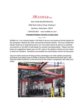
  • 1. MULTIFAB INCORPORATED 3808 North Sullivan Road, Building 6 Spokane, Washington, 99216 1-509-924-6631 www.multifab-inc.com THERMOFORMING DESIGN GUIDELINES (Revision 6-4-2009) Multifab Inc. is an industry leader in the field of vacuum and pressure formed plastics for the Aerospace, Medical and other commercial industrial markets. We have created this Design Guide as an engineering aid for our many good clients as well as our potential new partners in the effort to best design for process manufacturability. Please note that these are suggestions based upon our 25+ years in the plastics industry and are meant to direct as a baseline. Deviations are possible but would always need to be discussed. Vacuum and/or pressure formings primary advantage over other plastics processing techniques has always been its ability to produce three-dimensional parts with a rela- tively low initial investment in time and cost for the molds in comparison with other proc- esses. 1
  • 2. Table of Contents Materials………………………………………………... 3 Process Description– Vacuum Forming…………….. 4,5 Process Description– Pressure Forming……………. 6,7 Process Description– Twin Sheet Forming…………. 8,9 Dimensional Tolerances ……………………………… 10,11 Drawing Dimensioning………………………………… 12,13 Draw Ratio……………………………………………… 14,15 Plug Assist ……………………………………………... 16 Draft……………………………………………………... 17. Radius & Chamfers……………………………………. 19,20,21 Undercuts………………………………………………. 22,23,24 Textures………………………………………………… 25. Decorative Materials & Forming……………………... 26 Ribs and Louvers……………………………………… 27 Stiffener Elements…………………………………….. 28,29 Trim Holes & Features………………………………… 29,30,31 Fastening……………………………………………….. 33,36 Common Quality Problems…………………………… 35,36 Conclusion …………………………………………….. 37 Notes (blank pages)…………………………………… 38-40 2
  • 3. MATERIALS All thermoplastic materials can be and have been thermoformed at least experimentally. The high heat characteristics of the material must allow it to become soft enough to be stretched into a larger shape without becoming so weak that it separates during the forming or stretching process. Thermoplastics are split into two different groups– amorphous and crystalline. Crystal- line thermoplastics contain an ordered manner of molecules and amorphous contain a random arrangement. Generally speaking amorphous materials like polystyrene, ABS, polycarbonate, PVC, and PVC/Acrylic blends are easier to vacuum form as they do not have such a critical forming temperature. When heat is applied amorphous materials become soft and pli- able so when it reaches this state it is known as it Glass Transition Temperature (Tg). If heated to a higher temperature it reaches a Viscous state (Tv). The changes occur over a range of temperatures and enable the operator to have a fairly wide forming range. Semi-crystalline and crystalline materials such as polyethylene, polypropylene, TPO, and nylon have a far more critical forming temperature as they go rapidly from the Tg state to Tv a change known as the Melt Transition Temperature ™. When using crystal- line materials it is imperative that accurate temperature control is used to monitor the heating process. In summary, the forming temperatures bands for amorphous materials is much wider and a result are easier to process in comparison to their semi-crystalline counterparts. Uniform Material Distribution The cardinal rule for the design of all formed plastic parts is to try and maintain uniform material distribution. Thermo forming starts with a sheet of thermoplastic material which has a uniform wall thickness. This sheet of material may be somewhat thinned out by the stretching that takes place during the forming process. The thermoforming process operates at a temperature that softens but does not melt the material. These lower forming temperatures result in smaller differences in thermal expansion as the plastic material cools from the processing temperature down to room temperature. The lower processing temperatures, the gradual changes in wall thickness allow ther- moformed parts to be produced with relatively low levels of molded-in stress. These re- ductions in molded-in stress allow the production of tough parts which are dimensionally stable with less tendency toward post mold warpage. 3
  • 4. Process Description-Vacuum Forming The most widely used method of thermoforming is by use of vacuum. A male or female mold is moved into a hot sheet, and a vacuum is then used to remove the air trapped between the sheet and the mold. Thus atmospheric pressure (14.7 PSI @ sea level) is used to move the heated sheet into contact with the mold. This pressure holds the sheet until it cools below its Heat Distortion Temperature (HDT). All thermoforming techniques are stretching processes. The stretching of a flat sheet of plastic material into a larger shape results in a larger surface area and a corresponding reduction in the sheet's original thickness. The thinning down of the sheet's original thickness is not necessarily uniform. Processing techniques play a big part in material distribution. The portion of the sheet that first contacts the relatively cool die stretches and thins out the least. This is due primarily to the fact that the material that contacts the die first be- gins to cool and becomes stronger and therefore resists further stretching and thinning. Typical forming machine with process controls Infrared sensors, which is independent of ambient temperature, controls the exact sheet temperature before removing from oven prior to forming. 4
  • 6. Process Description-Pressure Forming When pressures greater than atmospheric (14.7 psi) are required to force the thermo- plastic into more intimate contact with the mold surface Pressure Forming is the an- swer. With the use of a pressure box on top of the sheet material, compressed air up from 80 to 120 PSI can be introduced to fully press the material on to the mold surface. This provides complex detail on the surface of the formed part with greater intimacy to the mold. Lockup bars holding tooling together. Lock up bar clamps compress tooling together. Among all of the thermoforming processes that are available, pressure forming offers the best chance of meeting challenging design criteria. The higher forming pressures associated with pressure forming provided the capability of producing parts with sharp, well-defined details. The use of higher forming pressure makes it possible to push the softened sheet into sharper, more clearly defined details. The very rapid forming speeds that are possible with these increased pressures, coupled with hotter dies, mini- mized the thinning. Solid plate machined with a raised edge lip to contact plastic sheet causing a seal on top of the sheet. Inside of edge lip pressure is applied to the sheet. Pressure plate Felt covered plug assist. Series of inflatable air bags are used to lift tool mounting plate increas- ing seal on plastic sheet Floating tool mounting plate. 6
  • 7. Pressure Forming- Process Steps Step 1 Step 2 Step 3 Step 4 Processing Sequence 1) Sheet is heated to thermoforming temperature. 2) Pressure forming equipment has features to lock together both sides of the pressure forming tool creating a seal on the plastic sheet. 3) The hot plastic sheet is then forced against a mold by introducing both com- pressed air on the top surface and vacuum in the tool cavity to evacuate the trapped air. 4) Part is removed from tooling and trimmed. 7
  • 8. Process Description-Twin Sheet Forming The twin sheet forming process is used to produce hollow parts. Two heated sheets are positioned between two female molds with matching perimeters or contact surfaces. The mold come together and heat seal the two sheets together where the molds meet. The process of injecting compressed air (20-120 p.s.i.) between two hot sheets, thus forcing it to conform to the contour of each of two molds mounted opposed to each other. Evacuation of the air between the sheet and the mold is required. The mold cav- ity contours may or may not be identical (pictured below).. 6 pound urethane foam is added to this part for stiffness. Both sides of the tool are used, the top forms first then the bottom portion. Both are compressed together while the material is still hot fusing the part halves together. Twin sheet forming has a lower tooling cost than blow molding and still produces a hol- low cavity and can be very structured with either side having structural design elements. 8
  • 9. Twin Sheet Forming—Processing Steps Step 1: Two preheated thermoplastic sheets are simultaneously heated between the two molds till they are entirely plasticized. Step 2: On reaching the specific temperature the sheet material is formed on top tool first then the bottom tool, and both parts are immediately compressed together fusing the joint flange. Step 3: To achieve a high level of detail or precision, needles enter the cavity and high pres- sure is added to compress the material against the tool surface. Step 4: Final configuration is one piece and the perimeter is trimmed. Rigid foam can be added to the interior for added strength. 9
  • 10. DIMENSIONAL TOLERANCES GUIDELINES: For molded in dimensions of parts from a machined aluminum male mold use +/-.010" for the first inch adding an additional +/-.001" for each subsequent inch. For female tools use +-.015 + .0015 due to process control loss of the material shrinking away from the tool surface during cool. Trimmed dimensions, regardless of the mold but us- ing CNC trimming equipment, should have a general tolerance of +/-.015". (see next page for chart). OVERVIEW: Thermoformed part tolerances are determined by the coefficient of thermal expansion of the resin, extrusion conditions, type and temperature of the mold, consistency of the forming process, method of trimming and quality of trimming fixtures. SPECIFICS: Most thermoforming resins have a coefficient of thermal expansion in the range of .000060" to .000120" per ºF per inch [6.0 - 12.0 x 10⁻⁵ in./ºF/in.]. This will be a more significant factor when the part is large and the "in use" temperature of the part varies. On parts over 48" it is good practice to add a note to the drawing specifying a tempera- ture at which the dimensions should be measured. We have found 40-50 ºF tempera- ture variances in our plant summer to winter. Extrusion quality will affect the part many ways. The control of the extruder from run to run is very important. Changes in extrusion speed, direction, temperature, and gauge will modify the amount of stress that the sheet has when it is delivered to the thermo- former. Differences in that stress will change the rate at which the part molds thus changing the dimensions. Molds must be temperature controlled with internal cooling channels to allow for con- sistent mold temperature. Aluminum is the material of choice because its very high co- efficient of thermal conductivity allows for very consistent cooling cycle times through the entire production run of parts. Wood, epoxy, or plaster do not allow for this. The forming process must be very consistent from run to run to insure dimensional consistency. The use of digital controls on the forming machine allows for a high de- gree of accuracy in the cycle times. A change in the amount of time the part spends in the mold has a direct effect on the amount of part shrinkage that occurs. The part must be held in the mold until the set temperature of the resin has been reached. We use digital controls on our forming equipment along with the capability to continually moni- tor the sheet temperature during the heating cycle for consistent processing. 10
  • 11. CNC trimming allows for tighter tolerances and consistent parts. A typical CNC trim- ming machine controls the movements to +/-.0002"; the trimming machine itself is de- signed for +/-.005. Please use this tolerance planning when designing your components: 1. Dimensioning scheme: Typically it is not customary to specify dimensions to the non-tool side of the part. This is due to the need to increase tolerancing significantly when including wall thickness variation. In such cases when tight tolerancing is needed on nontool side of parts, sec- ond operation machining may be considered. 2. Formed features: Male mold feature +/- .010” + .001 per inch (.3mm + .001mm per 1mm) Female mold feature +/- .015” + .0015 per inch (.4mm + .0015mm per 1mm) 3. Trimmed holes: Hole Dia. 1” and less +/- .010 (.3mm) Hole Dia. 1” to 5” +/- .015 (.4mm) Hole Dia. 5” + +/- .020 (.6mm) 4. Trimmed hole to hole: 1” and less +/- .010 (.3mm) 1” to 5” +/- .015 (.4mm) 5” + +/- .020 (.6mm) 5. Trim feature to molded feature: 1” to 5” +/- .020 (.6mm) 5” + +/- .030 (.8mm) 6. Trim feature to trim feature: 1” to 5” +/- .015 (.4mm) 5” + +/- .020 (.6mm) 11
  • 12. DRAWING DIMENSIONING GUIDELINES: All dimensions on the print should be generated from the mold side of the part. When possible the starting gauge of the sheet should be specified. OVERVIEW: One of the most common mistakes in thermoforming is that the dimensions are gener- ated from the non-mold surface of the part. Once the mold surface has been deter- mined there should be no confusion on dimensioning. All of the dimensions, formed in and trimmed in, must be referenced to the mold side of the part. Tooling side of part. Drawing controls this side of part. Notice sharp corner and un- controlled radius on outside of part. Tooling contact surface controls drawing. See drawing example on next page. 12
  • 13. Drawing example. Notice all the fea- tures are dimensioned to interior of part on tool side. “Anchor Points” on the drawing are easily measured. Holes and machine features are measured from a the tooling side of the part. When adding design features such as countersink please design with the final formed thickness in mind. So often the designs are completed in a “nominal wall” section and if the forming pro- duces thinning, then the wall final wall section may not be thick enough to meet the requirements. 13
  • 14. DRAW RATIO GUIDELINES: The deeper or taller the part the heavier the starting gauge of sheet required. Allowing the part or any feature of the part to be narrower than it is tall will thin the sheet at a much quicker rate. A 3:1 ratio is generally a maximum draw ratio. OVERVIEW: The draw ratio is the key to understanding thermoforming processes. The part has a fi- nite amount of surface area that needs to be covered by a flat two-dimensional sheet. When the sheet is heated and forced over or into a mold it must stretch to conform to that shape. As the sheet stretches it thins out, local design features on the part may cause the sheet to thin at a greater rate than in adjacent areas. SPECIFICS: The draw ratio can be described numerically if the surface area can be calculated. The formula for expressing the draw ratio is as follows: Draw Ratio = the Surface Area of the part / Footprint of the part Example #1: Assume a part is 10"x 12"x 2" deep. Therefore the Draw Ratio will be: Surface Area = 2(10" x 2") + 2(12"x2") + 10" x 12" = 40" + 48" + 120" = 208" Footprint = 10" x 12" = 120" Draw Ratio = 208"/120" = 1.7 If the desired ending wall thickness of the part is 0.100" use the draw ratio as follows to estimate the starting gauge of the sheet: Draw Ratio x Desired Finished Gauge = Minimum Starting Gauge 1.7 x 0.100" = .170" Assuming perfect material distribution. 14
  • 15. Example #2: Assume a part size of 10" x 11" x 5" deep. Surface Area = 2(10" x 5") + 2(11" x 5") + (10" x 11") = 300" Footprint = 10" x 11" = 110" Draw Ratio = 2.73 If the desired ending wall thickness is 0.100" use the draw ratio value as follows: 2.7 x 0.100" = .273" starting gauge. Assuming perfect material distribution. The above examples ignore the effect that a specific feature on the part (i.e.. a localized severe draw like a sharp corner) may have on the thinning of the sheet. The draw ratio is designed to get the part designer "in the ball park" when calculating the necessary starting gauge. Many part quotations will have two gauges specified (a high and low) because of the difficulty in predicting the proper starting gauge. Because the starting gauge is so critical to the cost of the part it is important to get proper feedback from Multifab when reviewing draw ratio. There are many thermoform- ing techniques and mold designs used to help the sheet stretch as uniformly as possi- ble. DEPTH OF DRAW The depth of draw ratio is defined as the ratio of the maximum depth of the female die and the minimum distance across the open face of the die at any given location on the die. It is generally recognized that the thermoforming process is at its best when the depth of draw ratio is less than 1 to 1. In other words, a part which is 12 inches across should not be more than 12 inches deep. The depth of draw ratio can be increased by combining other more complex forming procedures such as plug-assisted tool features or snap back and billow forming. These are common procedures used to increase the maximum depth of draw (see next page). Depth of draw distance 15
  • 16. PLUG ASSIST The purpose of a plug feature is two fold. It is used to prevent webbing in the forming of multiple male tools which are close together and to help achieve good wall thickness when forming into deep cavities. Under normal conditions plastic will start to thin radically once it exceeds in depth more than 75% of the cross section. The plug is used to push the heated material into a female tool prior or in conjunction with the vacuum being applied. It is used whenever large draw ratios are required. In most cases the plug assist facility is a feature suspended above the forming area. The majority of plug tools are simple in design and made from rigid foam or hardwood. A felt surface is often added to ensure the plug glides into the aperture without tearing or marking the plastic too much. Typically the depth of cavity can be 75% of the width of the opening on the surface. Excess thinning will occur beyond this depth. 16
  • 17. DRAFT GUIDELINES: For parts that are formed into a female mold with a texture allow 1 degree of draft plus 1 degree of draft for every thousandth of an inch of texture depth. With parts formed over a male mold allow 5 degrees of draft as a minimum and in female tools 3 degrees. OVERVIEW: The need for draft is driven by the coefficient of thermal expansion of the plastic. As the part is held in the mold it is cooled below the set temperature. This temperature change can be anywhere from 100 to 300 degrees depending on the resin. This change in tem- perature coupled with the coefficient of thermal expansion will cause the part to shrink. Draft also allows for better material distribution by opening up a corner area to allow clearance for a plug assist to push material. SPECIFICS: Parts can be molded with little or no draft. However, there is high probability that the part will not release from the mold or will have severe scuffing from any texture that is on the mold. By designing in draft the part is able to release from the mold much sooner in the release cycle. The greater the draft the quicker the release and the lower the risk of part hang-up or texture scuffing. Draft also "opens" up a corner (two or three sided) and allows for a better draw ratio. The drafted wall also allows for an assist plug to move material down into the mold with less risk of the plug hitting the sidewall. Almost every plastic molding process requires draft. In thermoforming the advantage of a one sided molding process becomes apparent with draft. In a female mold the mate- rial wants to shrink away from the sidewall of the mold. There is no mold "core" to pre- vent it from doing so. In this respect the shrink of the part actually helps keep the draft requirement to a minimum. On a male mold the part actually shrinks tighter on the mold making the draft requirement greater. A texture on the mold actually represents a series of undercuts in the mold. The deeper the texture, the greater the undercut and the greater the draft angle that will be required. Because on female molds the part shrinks away from the mold there is less chance the part will scuff during release. Points to remember are that any draft is better than no draft at all; and the larger the draft angle, the better, in keeping with the end-use requirements of the product. Pressure Formed parts will be easier to produce if they can be designed with 3 degrees minimum draft angles. 17
  • 18. Male mold with minimum inside draft. Notice thinning at the bottom of the part. 18
  • 19. RADII AND CHAMFERS GUIDELINES: Avoid a sharp three-sided corner by using a radius or chamfer. The radius at the bottom of the draw is most critical. The deeper the part the larger the radius or chamfer re- quired. OVERVIEW: The key to good part design in thermoforming is understanding the need for a proper size radius or chamfer. These features are typically needed to allow for part strength, retention of material thickness, and/or esthetics. SPECIFICS: One of the most difficult features in thermoforming is the three-sided sharp corner in a female mold. This feature accentuates the draw ratio because it forces the material to over the three walls as it is pushed into the corner. The material appears to stretch and thin out at a geometric rate, usually causing the material to either thin to an unaccept- able ending gauge or actually tear and create a hole in the part. A quick check to see if this condition is occurring is to hold a part up to a light source and inspect the corners to see if the gauge is so thin that light can be transmitted through the part. Many times the tool is constructed ignoring this problem, causing either a heavier starting gauge to be used or an adhesive filler applied to the inside of the part backing up the corner and adding strength. These "cures" will add significant cost to the part and should be avoided if at all possible. A common design technique is to use radii and/or a chamfers on the part, preventing the material from having to continue deeper into the corner, thus arresting the thinning hat would normally occur. The other advantage of radii and chamfers is that they distrib- ute stress over a larger area than a sharp 90 degree corner. A chamfer does not distrib- ute the stress as well as a radius, but it gives the designer the option of sharp corners at the transition points of the chamfer. Where a three-sided corner does occur, one large radius with a chamfer or smaller radius on the other edges is often sufficient to solve the thinning and strength problems that occur. As the draw ratio gets larger the radii will almost always have to be increased. Use this chart as a very rough rule of thumb to help determine the approximate radius you may need: Depth of Part Radius 0" - 3" .015" - .125" 3" - 6" .125" - .250" 6" - 12" .250" - ? 19
  • 20. Sometimes it may be necessary to prototype a particular corner or feature of the part prior to the start of mold construction. This is usually a quick method of answering any questions regarding material thickness questions. It is a well-known fact that there will be a gradual increase in stress in the corner of a plastic part whenever the size of the inside corner radius is less than 75% of the thick- ness of the wall. There will be a very rapid increase in stress when the inside corner ra- dius is less than 25% of the thickness of the wall to which the radius is attached. No radius on tooling equals high stress. If maximum strength is required, the size of the radius should be at least 75% of the thickness of the wall to which it is attached. This radius amount is uncontrolled Sharp fillets radius increase feature stress Good uniform radius design Generous radius minimize stress 20
  • 21. As marketplace preferences changed, designers began to ask for smaller outside radii. Pressure Forming, with its higher forming pressures, was able to give designers what they were asking for. Pressure Forming allows the forming of outside corner radii which are as small as .032 R inches with most materials and most shapes, however radius small than .050 R may need to be EDM machined rather than standard CNC milling which will increase the tooling cost. Pressure formed radius The designer must also remember that all plastic materials cannot be handled in the same way. Notch-sensitive materials such as nylon or polycarbonate are very suscepti- ble to a loss of strength in sharp corners. Other materials such as PVC and ABS are more tolerant of small corner radii. The shape of a part leading up to a corner also has an effect on the amount of thinning out of the sheet and the size of the corner radius that can be formed. The proper proportions for the corner radius on a plastic part will add significantly to the part's strength. The strength of radiuses corners is determined primarily by the size of the inside radius. Designers therefore tend to specify the inside corner radius on a plas- tic part. In the case of thermoformed parts, only that corner on the side of the part that comes into contact with the die can be controlled accurately. The designer must bear this fact in mind while specifying the corner radii on pressure formed parts. Adding reinforcement on the part’s backside may be a requirement if the corner is too sharp or the draw ratio is too great for the feature. 21
  • 22. UNDERCUTS (Pressure Forming) GUIDELINES: Keep the distance that the undercut projects into the part to a minimum. Typical under- cut sizes are .375" with some localized tabs of up to .500". Because the undercut will require even more stretching of the sheet stock it is important to keep the draw ratio in mind when designing for undercuts. OVERVIEW: Undercuts are a feature that can be added to thermoformed parts very cost effectively. Undercuts offer increased part strength, a locating edge, a fastening point, and/or the ability to hide a trimmed edge. Tooling costs will be increased, but not nearly the amount it would be if it were an injection molding or structural foam molding tool. SPECIFICS: Typically most undercuts are an inward facing flange. However, other types of under- cuts might include a reverse drafted wall, a molded in countersink or a design line that is not parallel to the direction of pull out of the mold. Because these features increase the surface area of the part they increase the draw ratio of the part. One of the most com- mon requests is to carry an undercut flange into one or all four corners of a part. The problem this presents is that it causes the material to stretch even more in an area that is typically the thinnest on the part, if it is a female tool. By stepping the undercut back in the corners you allow for better material distribution. Some undercuts do not require the mold to be collapsible or removable. The undercut may be small enough or the material flexible enough to allow the part to strip out of the mold. This is more likely to occur on a female mold because the part will shrink away from the sidewalls of the tool, as opposed to a male mold which finds the material shrinking tighter around it. Undercut areas (two sections) Tooling slides to relieve undercut If the undercut requires a moving section in the mold you must allow for a parting or wit- ness line on the part. This is not normally a problem on an undercut, which is an inward facing flange, since the parting line can be hidden at the point (see texture section) at which the part turns in. But on other undercuts there needs to be an allowance for the parting line. Many times the parting line is used as a point of demarcation between a textured and untextured surface. 22
  • 23. The safest way to incorporate an undercut in the mold is with an articulating section. the best long term approach is to incorporate the articulation of the undercut section within . Aluminum tool with pneumatic action slide to release undercut area. Undercut area in part. Notice the tooling slide witness line on the texture surface. Undercut section of part created with removable tooling section. Maxi- mum undercut amount is .500 23
  • 24. Undercut recessed part ledge for attach- ment of panel. Design ledge undercut to create a control design gap of mating part. Design ledge of .050/.060 is typical. Stepped in undercut to allow for attachment of mating part. Notice no texture is found in un- dercut area. Texture ends at start of radius. If texture is required in radius the tool will have a parting line at the tangent of the radius and be very visible. 24
  • 25. TEXTURES (Pressure Forming) GUIDELINES: The finer textures (.002" or less) are difficult to form in Pressure Forming. Coarser tex- tures allow for better replication and they also cover many mold or sheet imperfections. In vacuum forming the sheet is textured by the supplier. Pressure forming textures are the same as injection molding types and chemically etched into the tooling surface. Tooling insert lines can be easily seen in textures areas. 25
  • 26. DECORATIVE MATERIAL & FORMING The forming process has opened up a whole new market of appearance type parts for the thermoforming industry. Many parts come out of the die ready to use. However, the high quality appearance properties of decorative materials in formed parts bring them into some markets where visual aesthetics is important. Thermoformed parts can be hot stamped, silk screened, plated or embossed. Color can be provided in the original sheet or the parts can be totally or partially painted with smooth, satin or tex- tured paint. These decorating procedures can be performed in the same manner as would be required for any thermoplastic part produced by other processes. Laminate or decorated sheet can be used in thermo forming with amazing results. A variety of coated surfaces are available in sheet stock. Plastic sheet material can be extruded in multiple layers including clear surfaces and metallic colors for vibrant appearances with a high depth of clear coat surface. 26
  • 27. RIBS AND LOUVERS (Pressure Forming) GUIDELINES: The distance between each rib or louver should be greater than or equal to its depth. OVERVIEW: The ability of the material to form into the recesses created by the mold will deter- mine the dimensioning of the ribs or louvers. Typically the louvers are molded in and trimmed off from the back of the part. SPECIFICS: The ability to form in features relates directly back to the discussion of draw ratio. Material can be pushed into a recess but it might thin out to an unacceptable gauge. In other instances the sheet is unable to form into a recess because the sheet is thicker than the recess and the hot strength of the material will not allow it to form into the recess (see Draw Ratio page). Louvers can also be trimmed in with a CNC router. This, however, does not allow for a molded in return which would increase the strength of the louver and improve the appearance. Gaps should be 2x wall amount mini- mum. 27
  • 28. STIFFENER ELEMENTS Pressure Forming is capable of producing parts in numerous gauges. However, the cost advantages to be realized with the thinnest acceptable wall thickness are worth consideration. One way of achieving greater rigidity while keeping the nominal wall thickness to a minimum is the use of shapes that provide a stiffening or reinforcing ef- fect. Features in part stiffen surface Solid ribs of the type commonly used on injection and compression molded parts are not possible with thermoforming. It is generally accepted that the distance between the width of thermoformed stiffening rib should be at least 2 times the depth of the rib. Wider ribs may be required for relatively thick walled parts. Traditionally the edges of these ribs were always well radiused in order to minimize thinning out of the material as it stretched into the shape of the rib. The shape and lo- cation of stiffening ribs can be designed in many different ways to satisfy the needs of the part. Bonded in matching wall profile rail supports for added strength This type of ribbing can be used to add crush strength to a part. It is also obvious that all types of stiffening ribs could be added to supply a great deal of reinforcement to a thin wall product. 28
  • 29. Another approach to adding stiffness to a thin walled part is to add a slight dome crown or radius on large flat surfaces. A rise of as little as .015 inches per inch is enough to begin to provide a reinforcing effect. The slight dome also does a good job of hiding the warpage (or “oil canning” look ) which can sometimes be a problem with large, flat surfaces. Yet another type of stiffening that is common with thermoformed parts is the flange at the trim line at the open end of the part. These flanges provide a great deal of rein- forcement to a thin walled part. The presence of these relatively thick flanges often al- lows the use of thinner original sheet stock. This results in cost savings in both material and cycle time. Edge side wall adds greatly to the strength of the part. TRIMMED HOLES & FEATURES Louvers, holes, grills and other openings through the wail of thermoformed parts can- not be provided during the forming operation. These openings have to be cut, stamped or routed as a secondary operation. Pressure Forming tends to concentrate on parts which are produced in small-to- medium volumes. Routing side holes and other intricate shapes in these limited quan- tities is often preferred to the increases in tool cost to allow removal of the part during forming. Various CNC trimmed openings 29
  • 30. A side benefit of formed parts with their machined openings is that they do not contain the inherent weakness and surface appearance problems that are present on injection molded parts where the plastic separates to flow around an opening and then reunites on the opposite side to create a weld line. Routed openings through the side walls of formed parts give the designer an opportu- nity to use his imagination. The sizes, shapes and locations of routed openings are al- most endless. The size, position or configuration of these openings can be changed with no more effort than modifying the program. This allows the production of very small quantities of customized parts that would not be practical if mold modification were required for each special part. A few different types of openings that are routinely provided on formed parts. The round hole is the simplest type of opening. This hole can be round or square or any other shape imaginable. It can be a straight-through or angled hole. Its side walls can be straight or beveled. Holes can be routed through recessed areas. This approach has several advantages. The top outside appearance surface can have a nice smooth as formed surface. A ra- dius or recess or trim bead can be formed around the hole. The cut edges are re- cessed below the appearance surface. The walls that form the vertical portion of the recess provide reinforcement to the hole and make it stronger. .125 minimum slot width. Length of CNC tool can limit cut away Recessed hole areas, hole may need to be elongated depending on cut angle 5 axis cut reposition Trim to backside of part Open area are prone to cutter marks 30
  • 31. If the final part is to incorporate a multiplicity of similar holes such as a series of louver openings, it is helpful to design these openings with the router cutter simply passing across the top at the openings in one continuous movement. Formed holes Keep cored holes separated by at least 2 wall sections of space. Pressure Formed parts are normally produced using female dies. This allows the proc- ess to produce its exceptionally good-looking surfaces on the appearance side of the finished product. It is common practice to provide critical inside dimensions and locating surfaces by the use of the same computer controlled routing procedures that are used to produce openings in formed parts. In the case of large parts, these machined dimensions will often be more reliable than as-molded dimensions. Vacuum holding fixtures provide for consistent reproduction and require fixturing on tooling side of part for registration. 31
  • 32. TRIM FEATURES (Pressure Forming) With rare exceptions, Pressure Formed parts must be cut out of the original sheet to separate the finished part from that portion of the sheet that was used to clamp it into the forming machine. There are many ways to trim the final part out of the original sheet. In cases where inward projecting undercuts are being provided at the open end of the part, the trim line can be completely hidden from view. Mounting tabs in undercut area trimmed with CNC Formed in hole that is machined from the backside. 32
  • 33. FASTENING GUIDELINES: Thermoforming allows for molded in inserts or bosses. Many different types of fasteners are available to be added to the part after molding and trimming. Avoid the bonding of blocks, this adds cost to the part. OVERVIEW: Fastening is one of the most difficult issues to resolve in the design of thermoformed parts. This is because it is not possible to mold in a boss or insert without it being visible on both sides of the part. SPECIFICS: Using bonded plastic blocks with a hot staked brass insert is a standard option. You will have to consider the cost of the plastic block, the labor to bond it in place, the cost of the adhesive, the labor to machine the block to the correct height and add a hole for the fastener or insert, all are significant. There are a number of fasteners that work well with thermoformed parts. Mulitifab should be willing to assist you in working out the fastening requirements of your parts. Mechanical arm supports perpendicur positioning of the hot iron for heat installation of brass insert at the correct angle. 33
  • 34. Solid pegs are often added to formed parts by adhesive bonding or heat sealing. These machined or molded bosses and blocks can be given additional strength by pro- viding flanges, gusset plates or interconnecting ribs. Adhesively or solvent bonding of bosses with brass inserts. Bonded side blocks with brass inserts are possible to mounting positions 34
  • 35. COMMON QUALITY ISSUES Chill Marks or Drag off lines When raising a deep draw mold into a heated sheet, the point which first makes con- tact cools, reducing its flow characteristics and producing a uneven flow of material at the top which thins down the sidewalls as the vacuum is applied,. This can be elimi- nated by increasing the draft angles and ensuring the mold is not too cool. Chill marks lines on surface Webbing, Bridging, or Wrinkling Webbing occurs when the material shrinks back on itself. The cause is numerous such as the mold being too high in relation to it base area, sharp vertical corners with mini- mum draft angles, deep multiple molds in close proximity to each other, and excessive sheet material when using small molds, and too narrow of space between forming fea- tures. Too narrow of distance between side walls Webbing in corner 35
  • 36. Thinning: This is one of the most common problems with mold design and is the result of deep draw ratios and minimum draft angles. There are numerous solutions which includes pre-stretching the material, plug assist, adding strengthening rib into the part design, and increase internal draft angles. Part Warpage or Shrinkage Size issues: Add stiffening and break up large surface areas with ribs, fillets, and corrugations Mold sticking: Increase draft to relieve part demolding. Part Cracking: Increase radius on part design. Blisters or Bubbles, Pin Holes or Pimples, Shiny Streaks, shrink marks, loss of detail, scorching or degradation, whitening of formed part, blushing or change in color intensity: Common forming issues that can be corrected with proper processing controls. 36
  • 37. CONCLUSION We would like to thank you for taking the time to understand the process parameters sur- rounding the design implementation in Vacuum, Pressure and Twin Sheet Forming. It is a pleasure to work with clients who can design and create controls that support these types of plastics processes. We are always on call and available to help with any questions that you may have. Please consider Multifab to be a part of your “Design Team”. The following is a contact list of the appropriate personnel to meet your needs: Multifab Inc. Contact List President Tim Smith smith.t@multifab-inc.com Sales Manager Dean Cameron deanc@multifab-inc.com Engineering Manager Wes Yandt wesy@multifab-inc.com Purchasing Manager David Tobler davidt@multifab-inc.com Production Manager Mike Veale mikev@multifab-inc.com QA Manager Kevin Lunde kevinl@multifab-inc.com Sales Engineer Steve Fox stevef@multifab-inc.com http://www.multifab-inc.com 1-800-533-3360 Phone 1-509-928-2832 Fax 37