SlideShare ist ein Scribd-Unternehmen logo
1 von 12
Downloaden Sie, um offline zu lesen
UMTS RADIO INTERFACE SYSTEM PLANNING AND
               OPTIMIZATION
By: David Rottmayer, Vice President, Telefocal Asia


INTRODUCTION
The goal of the UMTS (universal mobile telecommunications system) is to deliver
multimedia services to the user in the mobile domain. UMTS and multimedia services
have a significant impact not only on the RF (radio frequency) network, but also on
the core network architecture. Care must be taken to allow current GSM (global
system mobile) operators to protect their infrastructure investments when their
networks are upgraded to support UMTS.
The UMTS network architecture is reflected in the below figure. The core network
handles call control and mobility management functionalities, while the UTRAN (UMTS
terrestrial radio access network) manages the radio packet transmission and resource
management.


Packet routing and transfer within the core network are supported by definition of
new logical network nodes called GGSN (gateway GPRS (general packet radio
system) support node) and SGSN (serving GPRS support node). The GGSN is basically
a packet router with additional mobility management features, and it connects with
various network management features, and it connects with various network
elements through standardised interfaces. The GGSN acts as a physical interface to
the external packet data networks (i.e. Internet). The SGSN handles packet delivery
to and from mobile terminals. Each SGSN is responsible for delivering packets to the
terminals within its serving area. GGSN and SGSN are capable of supporting terminal
data rates of 2Mbps or greater.
A UTRAN consists of one or more RNSs (radio network subsystems), which in turn consist
of base stations (Node Bs) and RNCs (radio network controllers). The RNS performs all
of the radio resource and air interface management functionalities. The UMTS
network architecture inherits most of its structure from the GSM model in the UTRAN.
This white paper focuses on the differences between GSM radio system planning and
UMTS radio system planning. UMTS uses WCDMA (wideband code division multiple
access) as the radio transmission technology. It is claimed that TDMA (time division
multiple access) RF planning is much more difficult that CDMA-based systems. This is
true, in part, because of the interference issues. However, UMTS serves users with
various demands, and many aspects of planning are more closely interrelated to
each other in UMTS planning than they are in GSM planning.
The major differences in the UMTS radio system planning process occur in coverage
and capacity planning. In GSM, coverage is planned separately after the network is
dimensioned (based on market study), and capacity and frequency are planned in
tandem. In UMTS, coverage and capacity are planned at the same time, because
capacity requirements and traffic distribution influence coverage. Frequency and
code can be planned separately. On the other hand, the wideband nature of
WCDMA technology (5MHz) compared with GSM (200kHz) imposes new criteria in
modelling the propagation environments.
This white paper outlines the challenges and solutions for planning and optimising
UMTS networks with respect to radio interface. WCDMA air interface specifications
and their implications on transmission channel behaviour and modelling are
described first. Next, solutions are provided for system design, including coverage,
capacity, code, and frequency planning. The analysis captures both design
processes and engineering calculations. The critical optimisation and monitoring of
WCDMA network performance are then discussed.              Finally, the white paper
concludes by summarising the results and presenting the future roadmap.


UMTS RADIO INTERFACE
WCDMA has been selected as the radio interface technology of UMTS networks for
much of the world. It is totally different from the technology used in GSM or TDMA.
The basic radio system planning philosophy used in GSM and TDMA does not change,
but almost all of the detailed planning items concerned (i.e. link budget, etc.) have
to be checked and adjusted to be suitable for WCDMA technology. In addition, the
radio system planning process has to be modified slightly form the traditional model
because the traffic can vary from 8kbps voice to 2Mbps data and can be either
circuit switched or packet switched.

WCDMA AIR INTERFACE SPECIFICATIONS
It is important to understand the basic UMTS air interface features to plan radio
interface of the network. The WCDMA specification has certain key features, which
re listed in the below table.
                  Parameter                                Value
     Modulation                          DS-CDMA with QPSK
     Chip rate                           3.84Mchip/s
     Duplexing                           FDD and TDD modes
     Channel Bandwidth                   5MHz with centre frequency raster of
                                         200KHz
     Service                             Multi-rate and multiservice
     Frame length                        10ms frame with 15 time slots
WCDMA air interface is based on DS-CDMA (direct sequence CDMA) technology.
The user data sequence is multiplied with a so-called spreading sequence, whose
symbol or chip rate is much higher than the user data rate. The relation between user
data rate and chip rate is called a spreading factor (SPF = Rchip/Rbit). The chip rate
in WCDMA is 3.84Mchip/s, and the spreading factors are in the range of 4 to 512;
therefore, the user net bit rates supported by one code channel are in the range of 1
to 936kbps in the downlink. Up to three parallel codes can be used for one user,
giving bit rates up to 2.3Mbps. In the uplink, data rates are half of these figures,
because of modulation differences.
The WCDMA standard includes two modes of operation: WCDMA/TDD (time division
duplexing) and WCDMA/FDD (frequency division duplexing). In WCDMA/FDD, the
uplink and downlink signals are at different frequency bands. In WCDMA/TDD, the
uplink and downlink signals are at the same frequency but are separated to different
time periods. 1
The nominal channel bandwidth of the WCDMA is 5MHz. The specification provides
the flexibility to define the exact channel centre frequency of 200kHz raster, so the
actual channel separation might be smaller than the nominal 5MHz, down to the
specified minimum 4.4MHz. This has to be noted carefully because it might cause
interference in the network.
The WCDMA transmission is split into 10ms radio frames, each of which consists of 15
pieces of 666ms (2560 chips) time slots. The bit rate and, for example, channel
coding can be changed in every 10-ms frame, offering very flexible control of the
user data rate. Every time slot has bits reserved for pilot signal, power control (TPC
bits), transport format indication (TFCI bits), and if necessary, closed loop transmit
diversity (FBI bits). The exact signal format and multiplexing are quite different in
uplink and downlink signalling. Also, the dedicated and shared channels have
several differences in signal format.

UMTS PROPAGATION ENVIRONMENT
The radio propagation channel environment is divided into outdoor and indoor
classes. The outdoor class is further divided into macro-cellular and microcellular
propagation environments. The macro-cellular type of environment can contain
different building densities (i.e. urban, suburban, rural, etc.).      Each of these
propagation environments has special radio propagation channel characteristics.
When considering the differences among GSM, TDMA, and UMTS radio interface
performances, the key channel property is the delay spread, which describes the
amount of multipath propagation in the propagation environment of the radio link.
The delay spread can be calculated from the typical (estimated or measured) power
delay profile, which describes the signal power as a function of the delay.
The effect of multipath on the radio channel can also be described by the frequency
domain properties of the radio channel. In the frequency domain, multipath causes
frequencies have different fading (amplitude and phase). One frequency domain
property of the channel is coherence bandwidth, Dfc. It can be calculated from the
time domain property of delay spread. Coherence bandwidth is the minimum
frequency separation of the two carriers that have significantly uncorrelated fading.
The table shows the calculated coherence bandwidths typical for different radio
propagation environments. The system is NB (narrowband) when the radio signal
bandwidth is much smaller than the coherence bandwidth of the radio channel and
WB (wideband) when it is much larger. Therefore, that system property is dependent
on the typical propagation environment in which the system is used and could differ
in different environments.


1 Most UMTS deployments thus far use FDD. One reason is spectrum; in countries such

as the United States, only limited spectrum is available for TDD.
Delay, µs        ∆fc, MHz          WCDMA              GSM
Bandwidth                                                BW = 5 MHz     BW = 0.2MHz
Urban                     0.5             0.32                SB            NB/WB
Rural                     0.1              1.6               WB               NB
Hilly                      3              0.053              WB               WB
Microcellular            <0.1             >1.6             NB/WB              NB
Indoor                   <0.01             >16               NB               NB
    Characteristics of GSM versus UMTS for Different Radio Propagation Environments
The coherence bandwidth is related to the correlation of fading over the transmission
bandwidth. In a propagation environment where a system is narrowband, fading is
frequency nonselective or flat. In the wideband environment, fading for signal
frequencies is uncorrelated and the fading is called frequency selective. Comparing
the chip duration (0.26ms) of WCDMA to the typical urban channel delay spread, it
can be seen that the delay spread is larger than the chip duration. A WCDMA
receiver achieves optimum performance by using all of the delay spread is larger
than the chip duration. A WCDMA receiver achieves optimum performance by using
all of the multipath components via a Rake receiver. The Rake receiver receives and
combines different multipath delayed elements of the received signal.             This
combining method is an advantage of WCDMA compared with GSM and TDMA
signals and increases the received signal power.


UMTS RADIO SYSTEM PLANNING
The implementation strategy must be planned carefully because UMTS is a totally
new system. UMTS operates in the frequency band of 2100MHz, which is much higher
than the 850MHZ, 900MHz, 1800MHz, and 1900MHz typically used in GSM and TDMA
systems. Also, the higher data rates for UMTS require better signal strength, Eb/No.
These operating frequency differences, plus the higher data rates, mean the radio
propagation will not be equivalent. As a result, the old base station coverage areas
are not necessarily valid in UMTS. Although reusing the old base station sites would be
very cost effective, they are not necessarily the most optimum locations for UMTS
coverage. The decision to reuse the base station sites depends heavily on the
implementation strategy and on the traffic forecasts.

UMTS RADIO SYSTEM PLANNING PROCESS
The UMTS radio system planning process is similar to the GSM planning process. The
phases of the planning process are:
   Dimensioning
   Configuration planning
   Coverage and capacity planning
   Code and frequency planning
   Parameter planning
   Optimisation and monitoring
The overall planning goal in any wireless system is to maximise coverage and
capacity while meeting the KPIs (key performance indicators) and QoS (quality of
service).
UMTS System Planning Process
The figure shows the UMTS planning process. In particular, the figure shows the one
key issue in UMTS coverage and capacity planning, namely that the traffic level has
to be considered continuously in UMTS radio planning.
The distribution of the traffic levels between voice and different data calls at each
base station coverage area should be determined as accurately as possible. Also,
the location of the different mobile users (or actually the link budget of each mobile
user) should be known as exactly as possible. It is, of course, impossible to know the
mobile user locations exactly; however, the more accurately they can be forecast,
the better the radio network can be designed.
Another key issue in WCDMA radio coverage and capacity planning is the regional
traffic distribution, or the existence of traffic hot spots in the radio network coverage
area. Base station locations should be selected so that they are always placed on
the traffic hot spots, since this offers the best link budget for the mobile users served
by those base stations. As the users move away from the base station, WCDMA
throughput decreases. As shown in the figure, placing base stations on traffic hot
spots significantly reduces power levels in the radio network, which reduces
interference and increases capacity.


           Correct UMTS Base Station Placement impacts system capacity
In the initial dimensioning phase, a fixed load is assumed for all base stations within
the targeted area. The value for the load can be the maximum acceptable load for
the cells or it can be the predicted load during the busy hour. If the highest
acceptable load is used, the dimensioning is done according to the worst-case
scenario, which may lead to an unnecessarily high number of sites. It is better to use
the predicted load, because it will give more realistic results.
In the detailed planning phase, the traffic distribution is used to allocate the
predicted traffic to the planned cells. This may lead to situations in which the load
between the cells can vary remarkably. Some cells may have a load very close to
the maximum acceptable load, and some cells may have a fairly low load.
Coverage targets must also be checked during this planning phase.
Although, in dimensioning, the traffic is assumed to be evenly distributed across a
particular area, in reality, each area may have a different traffic density. Also in
dimensioning, propagation is assumed to be similar for all cells and all cells are
assumed to be identical. During detailed planning, coverage predictions can be
quite different among the cells due to propagation environment and traffic
distribution. Typically, Monte-Carol distribution of the mobile stations is used to predict
instant traffic demands.

WCDMA TRANSMITTER, RECEIVER, AND CHANNEL PARAMETERS
WCDMA coverage planning begins from the link budget calculation. The link budget
in WCDMA, as in GSM, takes into account the base station equipment configuration
and the base station antenna line configuration. The WCDMA link budget also
contains some new parameters that are not used in the GSM link budget. A typical
link budget for WCDMA is presented the table labelled “Typical Link Budget for
WCDMA Cell”. The link budget is calculated based on the following assumptions:
   Uplink bit rate is 64kbps and downlink bit rate is 144kbps
   Predicted load in uplink is 30% and in downlink is 50%
   1W output power at the BTS (Node B) is reserved for a connection
The link budget in the table is divided into five parts. In general information, the
frequency band, chip rate, temperature and Boltzman’s constant are given. In
service information, the bit rates and loads for uplink and downlink are defined.
Receiving end and transmitting end define the ration links in the uplink and downlink
directions, respectively. Finally, isotropic path loss is defined as the maximum
expected path loss between the receiver and transmitter.
    General Information                  Units                        Value
Frequency                                MHz                           2100
Chip rate                                Mcps                          3.84
Temperature                                K                            293
Boltzman’s Constant                       J/K                       1.38E-23


Service Information            Units                             Urban
                                                     Uplink                Downlink
Load                            %                      30                    50
Bit Rate                       Kbps                   64.0                  144.0
Receiving End                Units           Uplink          Downlink
Thermal noise density                   dBm/Hz          -173.93           -173.93
Receiver noise figure                     dB              3.00               6.00
Receiver noise density                  dBm/Hz          -170.93            167.93
Noise power                              dBm            -105.09           -102.09
Interference margin                       dB              1.55              3.01
Receiver interference power              dBm            -108.77           -102.09
Total noise (thermal + interference)     dBm            -103.54            -99.08
Processing gain                           dB             17.78              14.26
Required Eb/No                            dB              5.00              4.00
Receiver Sensitivity                     dBm            -116.32           -109.34
Rx antenna gain                           dBi            18.00               0.00
Cable loss                                dB              4.00              0.00
LNA gain                                  dB              0.00              0.00
Antenna diversity gain                    dB              0.00              0.00
Soft handover diversity gain              dB              3.00              3.00
Power control headroom                    dB              0.00               0.00
Required signal power                    dBm           -133.332           -112.34
Field Strength                          dBµV/m           10.32             31.31
Z = 77.2 + 20*log(freq[MHz])


           Transmitting End                Units      Uplink             Downlink
TX power per connection                     W          0.126               1.00
TX power                                   dBm         21.00              30.00
Cable loss                                  dB          0.00               4.00
TX antenna gain                             dBi         0.00              18.00
Peak EIRP                                  dBm         21.00              44.00
Isotropic path loss                         dB        154.32              156.34
                          Typical Link Budget for WCDMA Cell

WCDMA COVERAGE AND CAPACITY PLANNING
Coverage and capacity planning in WCDMA are interrelated. In low traffic areas,
WCDMA planning is quite similar to GSM planning, because the load does not have
great impact on coverage. Of course, many details differ between the systems, but
the main principles can be applied to both. In high traffic areas, unlike for GSM, there
is no clear split between coverage, interference, and capacity planning in WCDMA.

Coverage Planning
The propagation predictions for WCDMA require the same planning phases as in
GSM. First, the base station configuration and the link budget have to be defined.
Also, the coverage threshold has to be well defined to exceed the required quality
criteria but avoid unnecessary additional investments for the radio network elements.
Moreover, the capacity targets and forecasts have to be well known at this phase
because they have a strong effect on the base station coverage area. When the
base station antenna height, coverage threshold, and capacity requirements are
defined and the base station configuration is clarified in the link budget calculations,
the actual propagation predictions process can start. Propagation measurements
can be performed to fine-tune the propagation prediction model. When the
prediction model is tuned, the final base station parameters can be used to make the
propagation predictions.
Optimised base station parameters can be evaluated when the planning criteria are
defined. This planning threshold means that agreement must be reached on the
reasonable QoS level required for the different geographical locations. The threshold
also depends on whether the service has to be extended inside vehicles and
buildings in different areas. The planning threshold is defined in GSM by starting from
the mobile station sensitivity (for the forward link) and by adding the required clutter
planning margins to the sensitivity value in each particular planning terrain bin.

Capacity Planning
WCDMA capacity planning is directly related to the link budget and, thus, to the
base station coverage area. In the link budget reflected in the table labelled
“Typical Link Budget for WCDMA Cell”, only one type of service (64/144kbps data
transmission) was introduced, and the base station coverage was fixed for this
service. It is possible to have any type of service between the voice calls and 2Mbps
data traffic in the WCDMA base station. This means that the base station coverage
area is different for different users.


         Relative Cell Range and Cell Area versus User Bit Rate Using WCDMA
 (Cell ranges calculated by using Okumura-Hata propagation formula and antenna
                                height of 25 meters)
Basically, the question is about the spreading factor, SPF, which varies significantly
when comparing the 12.2kbps voice call (SPF=25dB) and 2Mbps data transmission
(PG=2.8dB) connections.
In the uplink direction, the main objective in capacity planning is to limit interference
from the other cells to an acceptable level. Network planning can increase the
uplink load by reducing other cell interference. This can be achieved by using
buildings, hills, etc., as obstacles to block the interfering cells. Also, down-tilting is a
very useful tool to limiting interference. In the downlink direction, two aspects should
be considered: the interference from other cells and the power of the base station.
The load equation for the downlink is similar to the equation for the uplink. However,
in the downlink there is a new parameter called orthogonality. Orthogonality is a
measure of how much the users in the same cell do not interfere with each other. In
the downlink, users are much more orthogonal compared with uplink, because the
base station is transmitting to all the mobiles with very accurate timing of the
spreading codes.

WCDMA Code and Frequency Planning
In WCDMA, code and frequency planning are simple task from a network planning
point of view. The system takes care of most of the code allocation. The main task
for network planning is the allocation of scrambling codes for the downlink. There are
512 sets of scrambling codes available, so the code reuse for downlink is 512. This
means that code allocation is a relatively simple task, even though code capacity
does differ fro every user demand type. With more bandwidth user requests, a higher
level scrambling code is needed from the hierarchy of codes, and more code
resources are drawn on.
It is recommended that the allocation be done with the help of a planning system to
avoid the possibility for an error in the manual allocation. The number of codes used
in the early stages should be limited to allow for easier expansion of the network.
Frequency planning has minor importance compared with GSM. At most, UMTS
operators have two or three carriers, so there is not much to plan. However, the
operators have to make a few decisions.
   Which carrier(s) is used for macro cells?
   Which carrier(s) is used for micro cells?
   Is any carrier(s) reserved for indoor solutions?
When making these decisions, the interference aspects should be considered.
Carrier selection may affect intra-operator and inter-operator interference. For
example, micro-cells can cause high local interference for the operator’s macro cells
or anther operator’s macro or micro cells. Many potential problems can be solved by
proper network planning, and one of the techniques for solving these problems is to
properly select the frequencies.


WCDMA OPTIMISATION AND MONITORING
The WCDMA system, like the GSM system, needs continuous optimisation and
monitoring because the mobile users’ locations and traffic behaviour vary constantly.
This monitoring requirement is emphasised in WCDMA, as in al CDMA systems,
because the traffic demand can vary widely and this variation directly influences the
radio network quality. The better and more accurately the traffic amount and
locations can be modelled, the better and more efficiently (cost, quality, etc.) the
radio network can be designed and implemented.
The indicators that should be optimised and monitored are, for example:
  Traffic                                      Drop calls
  Traffic deviation                            Interference
  Traffic mixture                              Handovers per cell
  Soft handover percentage                     Inter-system handovers
  Average TX power                             Throughput
  Average RX power                             Bit error rate and frame error rate
Many of the listed indicators should be collected on a cell and service basis, because
the data may give hints on how to optimise the parameters to enhance the
performance of the network. A detailed discussion of the WCDMA system is out of
the scope of this white paper. However, three particularly important optimisation
challenges for WCDMA cell sites are examined: traffic load balancing, handoff
overhead management, and interference control.
The fundamental problem of traffic loading is that cellular traffic loading is that
cellular traffic is distributed unevenly among different geographical areas of the
network. In fact, even within cells traffic tends to be distributed unevenly among the
sectors.    Such imbalance has the effect of locking up network capacity in
underutilised sectors while causing blocking problems in the most heavily used
sectors. Balancing the traffic load among the sectors of a cell alleviates the blocking
and creates headroom for traffic growth. And by creating headroom at network
hotspots, a targeted traffic load-balancing strategy allows more traffic growth and
more efficient use of infrastructure and spectrum across the entire network.
One way of achieving load balancing is to modify the antenna orientation and
angular beamwidth of each sector to unify the traffic. This is possible using smart
array antennas, as shown in the figure below.


         Balancing Traffic Load and Boosting Capacity using Smart Antennas
Another aspect of WCDMA optimisation that directly affects cell site capacity is the
management of handoff overhead. The soft/softer handoff feature of the CDMA air
interface improves the quality and reliability of CDMA calls. However, because a
given mobile may be in contact with two or more cells or sectors at any given time,
as in areas A and B in the figure below, soft/softer handoff implies a significant cost in
capacity. After measuring the pilot strength in the area, the size of handoff zones
within the cell footprint should be decreased. Handoff zones should be shifted form
high-traffic areas to low-traffic areas.


 Example of Inefficient Design, Where a large area is covered by soft/softer handoff
Interference directly limits capacity of CDMA cell sites.          One of the biggest
interference problems in WCDMA network is pilot pollution. Pilot pollution is often
caused due to high-elevation sites with RF coverage footprints much larger than
normal. The solution is to reduce the size of the coverage footprint. This can be
accomplished by reducing the elevation of offending antennas, introducing downtilt,
or reducing the transmitted power.


CONCLUSIONS
The UMTS radio interface system planning has the same basic philosophy as GSM but
varies in the detail mainly because of two reasons: the change of radio propagation
channel that is a wideband type, and the change in modulation and transmission
mechanism that is DS-CDMA. The major subjects and findings are reflected in the
table below to summarise the major challenges concerning radio interface system
planning in UMTS.
         Subject                                     Finding
WCDMA radio                  Channel delay spread is larger than chip duration;
propagation channel           therefore, channel is wideband (frequency selective
                              fading)
                             Rake receiver takes into account multipath
WCDMA coverage               Coverage and capacity planning are related
and capacity                 Code planning is unique to WCDMA systems, while
planning process              channel planning is unique to GSM
                             Traffic information and forecasting are necessary in
                              coverage planning
WCDMA link budget            Planning covers the same basics as GSM, but uses
                              different parameters. The WCDMA link budget
                              depends on changes in bit rate and spreading factor
Capacity planning            Service depends on the distance from base station
Frequency planning           A simple process: the same frequency can be sued for
                              all the cells
Code planning                Allocation of scrambling codes is required for downlink
Optimisation and             These factors are greater importance than with GSM
monitoring
                UMTS Radio Interface System Planning and Optimisation
REFERENCES
1. T. Ojanpera and R. Prasad, “An Overview of Air Interface Multiple Access for IMT-
   2000/UMTS,” IEEE Communications Magazine, September 1998
2. European Telecommunications Standards Institute, GPRS, GSM, EDGE, and UMTS
   Standard Documents
3. M. Hata “Empirical Formula for Propagation Loss in Land Mobile radio Services,”
   IEEE Transactions on Vehicular Technology, Vol VT-29, No. 3, August 1980
4. E. Diran and B. Jabbari, “Spreading Codes in Direct Sequence CDMA and
   Wideband CDMA,” IEEE Communications Magazine September 1998
5. T. Ojanpera and R. Prasad, WCDMA: Towards IP Mobility and Mobile Internet,
   Artech house Publishers 2000
6. Viterbi “CDMA: Principles of Spread Spectrum Communication,” Addison-Wesley,
   1995
7. H. Holma and A. Toskala “HSDPA/HSUPA for UMTS; high Speed Radio Access for
   Mobile Communications,” Wiley, 2006C. Chevallier, C. Brunner, A. Garavaglia, K.
   Murray, and K. Baker, “WCDMA Deployment Handbook; Planning and
   Optimisation Aspects” Wiley 2006
8. J. Laiho, A. Wacker, and T. Novosad “Radio Network Planning and Optimisation
   for UMTS, 2nd Edition” Wiley 2006
9. http://www.umtsworld.com
10. http://www.3gamericas.org
11. Unicorn Communications UMTS Network Design and Optimisation Guidelines, Jan
    2010
12. 3GPP TS 25.201 Description
13. 3GPP TS 25.211 Physical channels and mapping of transport channels onto
    physical channels (FDD)
14. 3GPP TS 25.212 Multiplexing and channel coding (FDD)
15. 3GPP TS 25.213 Spreading and modulation (FDD)
16. 3GPP TS 25.214 Physical layer procedures (FDD)
17. 3GPP TS 25.215 Physical layer – Measurements (FDD)
18. 3GPP TS 25.855 High Speed Downlink Packet Access (HSDPA); Overall UTRAN
    description
19. 3GPP TS 25.856 High Speed Downlink Packet Access (HSDPA); Layer 2 and 3
    aspects
20. 3GPP TS 25.876 Multiple-Input Multiple-Output Antenna Processing for HSDPA
21. 3GPP TS 25.877 High Speed Downlink Packet Access (HSDPA) - Iub/Iur Protocol
    Aspects
22. 3GPP TS 25.890 High Speed Downlink Packet Access (HSDPA); User Equipment (UE)
    radio transmission and reception (FDD)

Weitere ähnliche Inhalte

Was ist angesagt?

2 drive test analysis ver1
2 drive test analysis ver12 drive test analysis ver1
2 drive test analysis ver1Virak Sou
 
2 g parameters_guidelines1
2 g parameters_guidelines12 g parameters_guidelines1
2 g parameters_guidelines1James Mutuku
 
Lte radio network planning huawei
Lte radio network planning huaweiLte radio network planning huawei
Lte radio network planning huaweitharinduwije
 
422738668-LTE-Downlink-Throughput-Optimization-Based-on-Performance-Data [Rep...
422738668-LTE-Downlink-Throughput-Optimization-Based-on-Performance-Data [Rep...422738668-LTE-Downlink-Throughput-Optimization-Based-on-Performance-Data [Rep...
422738668-LTE-Downlink-Throughput-Optimization-Based-on-Performance-Data [Rep...SudheeraIndrajith
 
RSCP RSSI EC/NO CQI
RSCP RSSI EC/NO CQIRSCP RSSI EC/NO CQI
RSCP RSSI EC/NO CQIFaraz Husain
 
GSM capacity planning
GSM capacity planningGSM capacity planning
GSM capacity planningDeepak Joshi
 
Part 1 fundamentals of 3 g
Part 1  fundamentals of 3 gPart 1  fundamentals of 3 g
Part 1 fundamentals of 3 gHenry Chikwendu
 
Base Station Antenna needs for the 5G RAN
Base Station Antenna needs for the 5G RANBase Station Antenna needs for the 5G RAN
Base Station Antenna needs for the 5G RAN3G4G
 
Ericsson important optimization parameters
Ericsson important optimization parametersEricsson important optimization parameters
Ericsson important optimization parametersPagla Knight
 
LTE Call Processing and Handover
LTE Call Processing and HandoverLTE Call Processing and Handover
LTE Call Processing and HandoverSitha Sok
 
3 g parameter ericsson
3 g parameter ericsson3 g parameter ericsson
3 g parameter ericssonMitul Shah
 
Drive Test Using Tems Investation 16
Drive Test Using Tems Investation 16Drive Test Using Tems Investation 16
Drive Test Using Tems Investation 16Md Joynal Abaden
 
Cs hs drop analysis and optimization presentation
Cs  hs drop analysis and optimization presentationCs  hs drop analysis and optimization presentation
Cs hs drop analysis and optimization presentationDaniel Amaning
 

Was ist angesagt? (20)

2 drive test analysis ver1
2 drive test analysis ver12 drive test analysis ver1
2 drive test analysis ver1
 
2 g parameters_guidelines1
2 g parameters_guidelines12 g parameters_guidelines1
2 g parameters_guidelines1
 
Lte radio network planning huawei
Lte radio network planning huaweiLte radio network planning huawei
Lte radio network planning huawei
 
422738668-LTE-Downlink-Throughput-Optimization-Based-on-Performance-Data [Rep...
422738668-LTE-Downlink-Throughput-Optimization-Based-on-Performance-Data [Rep...422738668-LTE-Downlink-Throughput-Optimization-Based-on-Performance-Data [Rep...
422738668-LTE-Downlink-Throughput-Optimization-Based-on-Performance-Data [Rep...
 
Irat handover basics
Irat handover basicsIrat handover basics
Irat handover basics
 
RSCP RSSI EC/NO CQI
RSCP RSSI EC/NO CQIRSCP RSSI EC/NO CQI
RSCP RSSI EC/NO CQI
 
Drive Test Nemo
Drive Test NemoDrive Test Nemo
Drive Test Nemo
 
TEMS PARAMETERS
TEMS PARAMETERSTEMS PARAMETERS
TEMS PARAMETERS
 
GSM capacity planning
GSM capacity planningGSM capacity planning
GSM capacity planning
 
Part 1 fundamentals of 3 g
Part 1  fundamentals of 3 gPart 1  fundamentals of 3 g
Part 1 fundamentals of 3 g
 
Base Station Antenna needs for the 5G RAN
Base Station Antenna needs for the 5G RANBase Station Antenna needs for the 5G RAN
Base Station Antenna needs for the 5G RAN
 
Ericsson important optimization parameters
Ericsson important optimization parametersEricsson important optimization parameters
Ericsson important optimization parameters
 
LTE Call Processing and Handover
LTE Call Processing and HandoverLTE Call Processing and Handover
LTE Call Processing and Handover
 
LTE Basics
LTE BasicsLTE Basics
LTE Basics
 
3 g parameter ericsson
3 g parameter ericsson3 g parameter ericsson
3 g parameter ericsson
 
Radio network overview
Radio network overviewRadio network overview
Radio network overview
 
Drive Test Using Tems Investation 16
Drive Test Using Tems Investation 16Drive Test Using Tems Investation 16
Drive Test Using Tems Investation 16
 
Lte optimization
Lte optimizationLte optimization
Lte optimization
 
UMTS Protocols
UMTS ProtocolsUMTS Protocols
UMTS Protocols
 
Cs hs drop analysis and optimization presentation
Cs  hs drop analysis and optimization presentationCs  hs drop analysis and optimization presentation
Cs hs drop analysis and optimization presentation
 

Andere mochten auch

3 g optimization interview topics
3 g optimization interview topics3 g optimization interview topics
3 g optimization interview topicsBouziane Beldjilali
 
3 g second carrier optimization report – cluster2_
3 g second carrier optimization report – cluster2_3 g second carrier optimization report – cluster2_
3 g second carrier optimization report – cluster2_Ridwan Syarif Siregar
 
3 g interview question & answer by telsol360
3 g interview question & answer  by telsol3603 g interview question & answer  by telsol360
3 g interview question & answer by telsol360Tel sol
 
Top 10 3 G Radio Optimisation Actions
Top 10 3 G Radio Optimisation ActionsTop 10 3 G Radio Optimisation Actions
Top 10 3 G Radio Optimisation ActionsAbdul Muin
 

Andere mochten auch (7)

3 g optimization interview topics
3 g optimization interview topics3 g optimization interview topics
3 g optimization interview topics
 
3G NEWORK OPTIMIZATION DOCUMENT
3G NEWORK OPTIMIZATION DOCUMENT3G NEWORK OPTIMIZATION DOCUMENT
3G NEWORK OPTIMIZATION DOCUMENT
 
3 g second carrier optimization report – cluster2_
3 g second carrier optimization report – cluster2_3 g second carrier optimization report – cluster2_
3 g second carrier optimization report – cluster2_
 
3 g interview question & answer by telsol360
3 g interview question & answer  by telsol3603 g interview question & answer  by telsol360
3 g interview question & answer by telsol360
 
Part 2 planning of 3G
Part 2  planning of 3GPart 2  planning of 3G
Part 2 planning of 3G
 
Top 10 3 G Radio Optimisation Actions
Top 10 3 G Radio Optimisation ActionsTop 10 3 G Radio Optimisation Actions
Top 10 3 G Radio Optimisation Actions
 
Part 3 optimization 3G
Part 3 optimization 3GPart 3 optimization 3G
Part 3 optimization 3G
 

Ähnlich wie Umts Radio Interface System Planning And Optimization

Ähnlich wie Umts Radio Interface System Planning And Optimization (20)

Wide band cdma
Wide band cdmaWide band cdma
Wide band cdma
 
Wireless networks gsm cdma
Wireless networks  gsm cdmaWireless networks  gsm cdma
Wireless networks gsm cdma
 
Report
ReportReport
Report
 
3G basic good
3G basic good3G basic good
3G basic good
 
3g basic
3g basic3g basic
3g basic
 
3gbasicgood-140728151357-phpapp02.pdf
3gbasicgood-140728151357-phpapp02.pdf3gbasicgood-140728151357-phpapp02.pdf
3gbasicgood-140728151357-phpapp02.pdf
 
Mobile Comm. - 3G Questions 1
Mobile Comm. - 3G Questions 1Mobile Comm. - 3G Questions 1
Mobile Comm. - 3G Questions 1
 
The impact of intermodulation interference in superimposed 2 g and 3g
The impact of intermodulation interference in superimposed 2 g and 3gThe impact of intermodulation interference in superimposed 2 g and 3g
The impact of intermodulation interference in superimposed 2 g and 3g
 
Performance Evaluation of QoS parameters in UMTS Network Using Qualnet
Performance Evaluation of QoS parameters in UMTS Network Using QualnetPerformance Evaluation of QoS parameters in UMTS Network Using Qualnet
Performance Evaluation of QoS parameters in UMTS Network Using Qualnet
 
WCDMA_new
WCDMA_newWCDMA_new
WCDMA_new
 
Mobile communication
Mobile communicationMobile communication
Mobile communication
 
Aa
AaAa
Aa
 
Long Term Evolution
Long Term EvolutionLong Term Evolution
Long Term Evolution
 
Umts services
Umts servicesUmts services
Umts services
 
Apr7.pdf
Apr7.pdfApr7.pdf
Apr7.pdf
 
3 G Interview
3 G Interview3 G Interview
3 G Interview
 
E0532630
E0532630E0532630
E0532630
 
DYNAMIC OPTIMIZATION OF OVERLAPAND- ADD LENGTH OVER MBOFDM SYSTEM BASED ON SN...
DYNAMIC OPTIMIZATION OF OVERLAPAND- ADD LENGTH OVER MBOFDM SYSTEM BASED ON SN...DYNAMIC OPTIMIZATION OF OVERLAPAND- ADD LENGTH OVER MBOFDM SYSTEM BASED ON SN...
DYNAMIC OPTIMIZATION OF OVERLAPAND- ADD LENGTH OVER MBOFDM SYSTEM BASED ON SN...
 
Dynamic optimization of overlap
Dynamic optimization of overlapDynamic optimization of overlap
Dynamic optimization of overlap
 
Unit i
Unit iUnit i
Unit i
 

Umts Radio Interface System Planning And Optimization

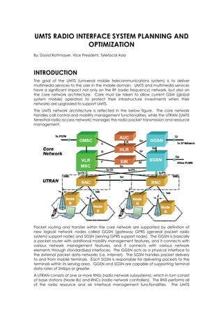
  • 1. UMTS RADIO INTERFACE SYSTEM PLANNING AND OPTIMIZATION By: David Rottmayer, Vice President, Telefocal Asia INTRODUCTION The goal of the UMTS (universal mobile telecommunications system) is to deliver multimedia services to the user in the mobile domain. UMTS and multimedia services have a significant impact not only on the RF (radio frequency) network, but also on the core network architecture. Care must be taken to allow current GSM (global system mobile) operators to protect their infrastructure investments when their networks are upgraded to support UMTS. The UMTS network architecture is reflected in the below figure. The core network handles call control and mobility management functionalities, while the UTRAN (UMTS terrestrial radio access network) manages the radio packet transmission and resource management. Packet routing and transfer within the core network are supported by definition of new logical network nodes called GGSN (gateway GPRS (general packet radio system) support node) and SGSN (serving GPRS support node). The GGSN is basically a packet router with additional mobility management features, and it connects with various network management features, and it connects with various network elements through standardised interfaces. The GGSN acts as a physical interface to the external packet data networks (i.e. Internet). The SGSN handles packet delivery to and from mobile terminals. Each SGSN is responsible for delivering packets to the terminals within its serving area. GGSN and SGSN are capable of supporting terminal data rates of 2Mbps or greater. A UTRAN consists of one or more RNSs (radio network subsystems), which in turn consist of base stations (Node Bs) and RNCs (radio network controllers). The RNS performs all of the radio resource and air interface management functionalities. The UMTS
  • 2. network architecture inherits most of its structure from the GSM model in the UTRAN. This white paper focuses on the differences between GSM radio system planning and UMTS radio system planning. UMTS uses WCDMA (wideband code division multiple access) as the radio transmission technology. It is claimed that TDMA (time division multiple access) RF planning is much more difficult that CDMA-based systems. This is true, in part, because of the interference issues. However, UMTS serves users with various demands, and many aspects of planning are more closely interrelated to each other in UMTS planning than they are in GSM planning. The major differences in the UMTS radio system planning process occur in coverage and capacity planning. In GSM, coverage is planned separately after the network is dimensioned (based on market study), and capacity and frequency are planned in tandem. In UMTS, coverage and capacity are planned at the same time, because capacity requirements and traffic distribution influence coverage. Frequency and code can be planned separately. On the other hand, the wideband nature of WCDMA technology (5MHz) compared with GSM (200kHz) imposes new criteria in modelling the propagation environments. This white paper outlines the challenges and solutions for planning and optimising UMTS networks with respect to radio interface. WCDMA air interface specifications and their implications on transmission channel behaviour and modelling are described first. Next, solutions are provided for system design, including coverage, capacity, code, and frequency planning. The analysis captures both design processes and engineering calculations. The critical optimisation and monitoring of WCDMA network performance are then discussed. Finally, the white paper concludes by summarising the results and presenting the future roadmap. UMTS RADIO INTERFACE WCDMA has been selected as the radio interface technology of UMTS networks for much of the world. It is totally different from the technology used in GSM or TDMA. The basic radio system planning philosophy used in GSM and TDMA does not change, but almost all of the detailed planning items concerned (i.e. link budget, etc.) have to be checked and adjusted to be suitable for WCDMA technology. In addition, the radio system planning process has to be modified slightly form the traditional model because the traffic can vary from 8kbps voice to 2Mbps data and can be either circuit switched or packet switched. WCDMA AIR INTERFACE SPECIFICATIONS It is important to understand the basic UMTS air interface features to plan radio interface of the network. The WCDMA specification has certain key features, which re listed in the below table. Parameter Value Modulation DS-CDMA with QPSK Chip rate 3.84Mchip/s Duplexing FDD and TDD modes Channel Bandwidth 5MHz with centre frequency raster of 200KHz Service Multi-rate and multiservice Frame length 10ms frame with 15 time slots WCDMA air interface is based on DS-CDMA (direct sequence CDMA) technology. The user data sequence is multiplied with a so-called spreading sequence, whose symbol or chip rate is much higher than the user data rate. The relation between user data rate and chip rate is called a spreading factor (SPF = Rchip/Rbit). The chip rate in WCDMA is 3.84Mchip/s, and the spreading factors are in the range of 4 to 512;
  • 3. therefore, the user net bit rates supported by one code channel are in the range of 1 to 936kbps in the downlink. Up to three parallel codes can be used for one user, giving bit rates up to 2.3Mbps. In the uplink, data rates are half of these figures, because of modulation differences. The WCDMA standard includes two modes of operation: WCDMA/TDD (time division duplexing) and WCDMA/FDD (frequency division duplexing). In WCDMA/FDD, the uplink and downlink signals are at different frequency bands. In WCDMA/TDD, the uplink and downlink signals are at the same frequency but are separated to different time periods. 1 The nominal channel bandwidth of the WCDMA is 5MHz. The specification provides the flexibility to define the exact channel centre frequency of 200kHz raster, so the actual channel separation might be smaller than the nominal 5MHz, down to the specified minimum 4.4MHz. This has to be noted carefully because it might cause interference in the network. The WCDMA transmission is split into 10ms radio frames, each of which consists of 15 pieces of 666ms (2560 chips) time slots. The bit rate and, for example, channel coding can be changed in every 10-ms frame, offering very flexible control of the user data rate. Every time slot has bits reserved for pilot signal, power control (TPC bits), transport format indication (TFCI bits), and if necessary, closed loop transmit diversity (FBI bits). The exact signal format and multiplexing are quite different in uplink and downlink signalling. Also, the dedicated and shared channels have several differences in signal format. UMTS PROPAGATION ENVIRONMENT The radio propagation channel environment is divided into outdoor and indoor classes. The outdoor class is further divided into macro-cellular and microcellular propagation environments. The macro-cellular type of environment can contain different building densities (i.e. urban, suburban, rural, etc.). Each of these propagation environments has special radio propagation channel characteristics. When considering the differences among GSM, TDMA, and UMTS radio interface performances, the key channel property is the delay spread, which describes the amount of multipath propagation in the propagation environment of the radio link. The delay spread can be calculated from the typical (estimated or measured) power delay profile, which describes the signal power as a function of the delay. The effect of multipath on the radio channel can also be described by the frequency domain properties of the radio channel. In the frequency domain, multipath causes frequencies have different fading (amplitude and phase). One frequency domain property of the channel is coherence bandwidth, Dfc. It can be calculated from the time domain property of delay spread. Coherence bandwidth is the minimum frequency separation of the two carriers that have significantly uncorrelated fading. The table shows the calculated coherence bandwidths typical for different radio propagation environments. The system is NB (narrowband) when the radio signal bandwidth is much smaller than the coherence bandwidth of the radio channel and WB (wideband) when it is much larger. Therefore, that system property is dependent on the typical propagation environment in which the system is used and could differ in different environments. 1 Most UMTS deployments thus far use FDD. One reason is spectrum; in countries such as the United States, only limited spectrum is available for TDD.
  • 4. Delay, µs ∆fc, MHz WCDMA GSM Bandwidth BW = 5 MHz BW = 0.2MHz Urban 0.5 0.32 SB NB/WB Rural 0.1 1.6 WB NB Hilly 3 0.053 WB WB Microcellular <0.1 >1.6 NB/WB NB Indoor <0.01 >16 NB NB Characteristics of GSM versus UMTS for Different Radio Propagation Environments The coherence bandwidth is related to the correlation of fading over the transmission bandwidth. In a propagation environment where a system is narrowband, fading is frequency nonselective or flat. In the wideband environment, fading for signal frequencies is uncorrelated and the fading is called frequency selective. Comparing the chip duration (0.26ms) of WCDMA to the typical urban channel delay spread, it can be seen that the delay spread is larger than the chip duration. A WCDMA receiver achieves optimum performance by using all of the delay spread is larger than the chip duration. A WCDMA receiver achieves optimum performance by using all of the multipath components via a Rake receiver. The Rake receiver receives and combines different multipath delayed elements of the received signal. This combining method is an advantage of WCDMA compared with GSM and TDMA signals and increases the received signal power. UMTS RADIO SYSTEM PLANNING The implementation strategy must be planned carefully because UMTS is a totally new system. UMTS operates in the frequency band of 2100MHz, which is much higher than the 850MHZ, 900MHz, 1800MHz, and 1900MHz typically used in GSM and TDMA systems. Also, the higher data rates for UMTS require better signal strength, Eb/No. These operating frequency differences, plus the higher data rates, mean the radio propagation will not be equivalent. As a result, the old base station coverage areas are not necessarily valid in UMTS. Although reusing the old base station sites would be very cost effective, they are not necessarily the most optimum locations for UMTS coverage. The decision to reuse the base station sites depends heavily on the implementation strategy and on the traffic forecasts. UMTS RADIO SYSTEM PLANNING PROCESS The UMTS radio system planning process is similar to the GSM planning process. The phases of the planning process are:  Dimensioning  Configuration planning  Coverage and capacity planning  Code and frequency planning  Parameter planning  Optimisation and monitoring The overall planning goal in any wireless system is to maximise coverage and capacity while meeting the KPIs (key performance indicators) and QoS (quality of service).
  • 5. UMTS System Planning Process The figure shows the UMTS planning process. In particular, the figure shows the one key issue in UMTS coverage and capacity planning, namely that the traffic level has to be considered continuously in UMTS radio planning. The distribution of the traffic levels between voice and different data calls at each base station coverage area should be determined as accurately as possible. Also, the location of the different mobile users (or actually the link budget of each mobile user) should be known as exactly as possible. It is, of course, impossible to know the mobile user locations exactly; however, the more accurately they can be forecast, the better the radio network can be designed. Another key issue in WCDMA radio coverage and capacity planning is the regional traffic distribution, or the existence of traffic hot spots in the radio network coverage area. Base station locations should be selected so that they are always placed on the traffic hot spots, since this offers the best link budget for the mobile users served by those base stations. As the users move away from the base station, WCDMA throughput decreases. As shown in the figure, placing base stations on traffic hot spots significantly reduces power levels in the radio network, which reduces interference and increases capacity. Correct UMTS Base Station Placement impacts system capacity
  • 6. In the initial dimensioning phase, a fixed load is assumed for all base stations within the targeted area. The value for the load can be the maximum acceptable load for the cells or it can be the predicted load during the busy hour. If the highest acceptable load is used, the dimensioning is done according to the worst-case scenario, which may lead to an unnecessarily high number of sites. It is better to use the predicted load, because it will give more realistic results. In the detailed planning phase, the traffic distribution is used to allocate the predicted traffic to the planned cells. This may lead to situations in which the load between the cells can vary remarkably. Some cells may have a load very close to the maximum acceptable load, and some cells may have a fairly low load. Coverage targets must also be checked during this planning phase. Although, in dimensioning, the traffic is assumed to be evenly distributed across a particular area, in reality, each area may have a different traffic density. Also in dimensioning, propagation is assumed to be similar for all cells and all cells are assumed to be identical. During detailed planning, coverage predictions can be quite different among the cells due to propagation environment and traffic distribution. Typically, Monte-Carol distribution of the mobile stations is used to predict instant traffic demands. WCDMA TRANSMITTER, RECEIVER, AND CHANNEL PARAMETERS WCDMA coverage planning begins from the link budget calculation. The link budget in WCDMA, as in GSM, takes into account the base station equipment configuration and the base station antenna line configuration. The WCDMA link budget also contains some new parameters that are not used in the GSM link budget. A typical link budget for WCDMA is presented the table labelled “Typical Link Budget for WCDMA Cell”. The link budget is calculated based on the following assumptions:  Uplink bit rate is 64kbps and downlink bit rate is 144kbps  Predicted load in uplink is 30% and in downlink is 50%  1W output power at the BTS (Node B) is reserved for a connection The link budget in the table is divided into five parts. In general information, the frequency band, chip rate, temperature and Boltzman’s constant are given. In service information, the bit rates and loads for uplink and downlink are defined. Receiving end and transmitting end define the ration links in the uplink and downlink directions, respectively. Finally, isotropic path loss is defined as the maximum expected path loss between the receiver and transmitter. General Information Units Value Frequency MHz 2100 Chip rate Mcps 3.84 Temperature K 293 Boltzman’s Constant J/K 1.38E-23 Service Information Units Urban Uplink Downlink Load % 30 50 Bit Rate Kbps 64.0 144.0
  • 7. Receiving End Units Uplink Downlink Thermal noise density dBm/Hz -173.93 -173.93 Receiver noise figure dB 3.00 6.00 Receiver noise density dBm/Hz -170.93 167.93 Noise power dBm -105.09 -102.09 Interference margin dB 1.55 3.01 Receiver interference power dBm -108.77 -102.09 Total noise (thermal + interference) dBm -103.54 -99.08 Processing gain dB 17.78 14.26 Required Eb/No dB 5.00 4.00 Receiver Sensitivity dBm -116.32 -109.34 Rx antenna gain dBi 18.00 0.00 Cable loss dB 4.00 0.00 LNA gain dB 0.00 0.00 Antenna diversity gain dB 0.00 0.00 Soft handover diversity gain dB 3.00 3.00 Power control headroom dB 0.00 0.00 Required signal power dBm -133.332 -112.34 Field Strength dBµV/m 10.32 31.31 Z = 77.2 + 20*log(freq[MHz]) Transmitting End Units Uplink Downlink TX power per connection W 0.126 1.00 TX power dBm 21.00 30.00 Cable loss dB 0.00 4.00 TX antenna gain dBi 0.00 18.00 Peak EIRP dBm 21.00 44.00 Isotropic path loss dB 154.32 156.34 Typical Link Budget for WCDMA Cell WCDMA COVERAGE AND CAPACITY PLANNING Coverage and capacity planning in WCDMA are interrelated. In low traffic areas, WCDMA planning is quite similar to GSM planning, because the load does not have great impact on coverage. Of course, many details differ between the systems, but the main principles can be applied to both. In high traffic areas, unlike for GSM, there is no clear split between coverage, interference, and capacity planning in WCDMA. Coverage Planning The propagation predictions for WCDMA require the same planning phases as in GSM. First, the base station configuration and the link budget have to be defined. Also, the coverage threshold has to be well defined to exceed the required quality criteria but avoid unnecessary additional investments for the radio network elements. Moreover, the capacity targets and forecasts have to be well known at this phase because they have a strong effect on the base station coverage area. When the base station antenna height, coverage threshold, and capacity requirements are defined and the base station configuration is clarified in the link budget calculations, the actual propagation predictions process can start. Propagation measurements can be performed to fine-tune the propagation prediction model. When the prediction model is tuned, the final base station parameters can be used to make the propagation predictions. Optimised base station parameters can be evaluated when the planning criteria are defined. This planning threshold means that agreement must be reached on the reasonable QoS level required for the different geographical locations. The threshold
  • 8. also depends on whether the service has to be extended inside vehicles and buildings in different areas. The planning threshold is defined in GSM by starting from the mobile station sensitivity (for the forward link) and by adding the required clutter planning margins to the sensitivity value in each particular planning terrain bin. Capacity Planning WCDMA capacity planning is directly related to the link budget and, thus, to the base station coverage area. In the link budget reflected in the table labelled “Typical Link Budget for WCDMA Cell”, only one type of service (64/144kbps data transmission) was introduced, and the base station coverage was fixed for this service. It is possible to have any type of service between the voice calls and 2Mbps data traffic in the WCDMA base station. This means that the base station coverage area is different for different users. Relative Cell Range and Cell Area versus User Bit Rate Using WCDMA (Cell ranges calculated by using Okumura-Hata propagation formula and antenna height of 25 meters) Basically, the question is about the spreading factor, SPF, which varies significantly when comparing the 12.2kbps voice call (SPF=25dB) and 2Mbps data transmission (PG=2.8dB) connections. In the uplink direction, the main objective in capacity planning is to limit interference from the other cells to an acceptable level. Network planning can increase the uplink load by reducing other cell interference. This can be achieved by using buildings, hills, etc., as obstacles to block the interfering cells. Also, down-tilting is a very useful tool to limiting interference. In the downlink direction, two aspects should be considered: the interference from other cells and the power of the base station. The load equation for the downlink is similar to the equation for the uplink. However, in the downlink there is a new parameter called orthogonality. Orthogonality is a measure of how much the users in the same cell do not interfere with each other. In the downlink, users are much more orthogonal compared with uplink, because the base station is transmitting to all the mobiles with very accurate timing of the
  • 9. spreading codes. WCDMA Code and Frequency Planning In WCDMA, code and frequency planning are simple task from a network planning point of view. The system takes care of most of the code allocation. The main task for network planning is the allocation of scrambling codes for the downlink. There are 512 sets of scrambling codes available, so the code reuse for downlink is 512. This means that code allocation is a relatively simple task, even though code capacity does differ fro every user demand type. With more bandwidth user requests, a higher level scrambling code is needed from the hierarchy of codes, and more code resources are drawn on. It is recommended that the allocation be done with the help of a planning system to avoid the possibility for an error in the manual allocation. The number of codes used in the early stages should be limited to allow for easier expansion of the network. Frequency planning has minor importance compared with GSM. At most, UMTS operators have two or three carriers, so there is not much to plan. However, the operators have to make a few decisions.  Which carrier(s) is used for macro cells?  Which carrier(s) is used for micro cells?  Is any carrier(s) reserved for indoor solutions? When making these decisions, the interference aspects should be considered. Carrier selection may affect intra-operator and inter-operator interference. For example, micro-cells can cause high local interference for the operator’s macro cells or anther operator’s macro or micro cells. Many potential problems can be solved by proper network planning, and one of the techniques for solving these problems is to properly select the frequencies. WCDMA OPTIMISATION AND MONITORING The WCDMA system, like the GSM system, needs continuous optimisation and monitoring because the mobile users’ locations and traffic behaviour vary constantly. This monitoring requirement is emphasised in WCDMA, as in al CDMA systems, because the traffic demand can vary widely and this variation directly influences the radio network quality. The better and more accurately the traffic amount and locations can be modelled, the better and more efficiently (cost, quality, etc.) the radio network can be designed and implemented. The indicators that should be optimised and monitored are, for example:  Traffic  Drop calls  Traffic deviation  Interference  Traffic mixture  Handovers per cell  Soft handover percentage  Inter-system handovers  Average TX power  Throughput  Average RX power  Bit error rate and frame error rate Many of the listed indicators should be collected on a cell and service basis, because the data may give hints on how to optimise the parameters to enhance the performance of the network. A detailed discussion of the WCDMA system is out of the scope of this white paper. However, three particularly important optimisation challenges for WCDMA cell sites are examined: traffic load balancing, handoff overhead management, and interference control. The fundamental problem of traffic loading is that cellular traffic loading is that cellular traffic is distributed unevenly among different geographical areas of the
  • 10. network. In fact, even within cells traffic tends to be distributed unevenly among the sectors. Such imbalance has the effect of locking up network capacity in underutilised sectors while causing blocking problems in the most heavily used sectors. Balancing the traffic load among the sectors of a cell alleviates the blocking and creates headroom for traffic growth. And by creating headroom at network hotspots, a targeted traffic load-balancing strategy allows more traffic growth and more efficient use of infrastructure and spectrum across the entire network. One way of achieving load balancing is to modify the antenna orientation and angular beamwidth of each sector to unify the traffic. This is possible using smart array antennas, as shown in the figure below. Balancing Traffic Load and Boosting Capacity using Smart Antennas Another aspect of WCDMA optimisation that directly affects cell site capacity is the management of handoff overhead. The soft/softer handoff feature of the CDMA air interface improves the quality and reliability of CDMA calls. However, because a given mobile may be in contact with two or more cells or sectors at any given time, as in areas A and B in the figure below, soft/softer handoff implies a significant cost in capacity. After measuring the pilot strength in the area, the size of handoff zones within the cell footprint should be decreased. Handoff zones should be shifted form high-traffic areas to low-traffic areas. Example of Inefficient Design, Where a large area is covered by soft/softer handoff Interference directly limits capacity of CDMA cell sites. One of the biggest
  • 11. interference problems in WCDMA network is pilot pollution. Pilot pollution is often caused due to high-elevation sites with RF coverage footprints much larger than normal. The solution is to reduce the size of the coverage footprint. This can be accomplished by reducing the elevation of offending antennas, introducing downtilt, or reducing the transmitted power. CONCLUSIONS The UMTS radio interface system planning has the same basic philosophy as GSM but varies in the detail mainly because of two reasons: the change of radio propagation channel that is a wideband type, and the change in modulation and transmission mechanism that is DS-CDMA. The major subjects and findings are reflected in the table below to summarise the major challenges concerning radio interface system planning in UMTS. Subject Finding WCDMA radio  Channel delay spread is larger than chip duration; propagation channel therefore, channel is wideband (frequency selective fading)  Rake receiver takes into account multipath WCDMA coverage  Coverage and capacity planning are related and capacity  Code planning is unique to WCDMA systems, while planning process channel planning is unique to GSM  Traffic information and forecasting are necessary in coverage planning WCDMA link budget  Planning covers the same basics as GSM, but uses different parameters. The WCDMA link budget depends on changes in bit rate and spreading factor Capacity planning  Service depends on the distance from base station Frequency planning  A simple process: the same frequency can be sued for all the cells Code planning  Allocation of scrambling codes is required for downlink Optimisation and  These factors are greater importance than with GSM monitoring UMTS Radio Interface System Planning and Optimisation
  • 12. REFERENCES 1. T. Ojanpera and R. Prasad, “An Overview of Air Interface Multiple Access for IMT- 2000/UMTS,” IEEE Communications Magazine, September 1998 2. European Telecommunications Standards Institute, GPRS, GSM, EDGE, and UMTS Standard Documents 3. M. Hata “Empirical Formula for Propagation Loss in Land Mobile radio Services,” IEEE Transactions on Vehicular Technology, Vol VT-29, No. 3, August 1980 4. E. Diran and B. Jabbari, “Spreading Codes in Direct Sequence CDMA and Wideband CDMA,” IEEE Communications Magazine September 1998 5. T. Ojanpera and R. Prasad, WCDMA: Towards IP Mobility and Mobile Internet, Artech house Publishers 2000 6. Viterbi “CDMA: Principles of Spread Spectrum Communication,” Addison-Wesley, 1995 7. H. Holma and A. Toskala “HSDPA/HSUPA for UMTS; high Speed Radio Access for Mobile Communications,” Wiley, 2006C. Chevallier, C. Brunner, A. Garavaglia, K. Murray, and K. Baker, “WCDMA Deployment Handbook; Planning and Optimisation Aspects” Wiley 2006 8. J. Laiho, A. Wacker, and T. Novosad “Radio Network Planning and Optimisation for UMTS, 2nd Edition” Wiley 2006 9. http://www.umtsworld.com 10. http://www.3gamericas.org 11. Unicorn Communications UMTS Network Design and Optimisation Guidelines, Jan 2010 12. 3GPP TS 25.201 Description 13. 3GPP TS 25.211 Physical channels and mapping of transport channels onto physical channels (FDD) 14. 3GPP TS 25.212 Multiplexing and channel coding (FDD) 15. 3GPP TS 25.213 Spreading and modulation (FDD) 16. 3GPP TS 25.214 Physical layer procedures (FDD) 17. 3GPP TS 25.215 Physical layer – Measurements (FDD) 18. 3GPP TS 25.855 High Speed Downlink Packet Access (HSDPA); Overall UTRAN description 19. 3GPP TS 25.856 High Speed Downlink Packet Access (HSDPA); Layer 2 and 3 aspects 20. 3GPP TS 25.876 Multiple-Input Multiple-Output Antenna Processing for HSDPA 21. 3GPP TS 25.877 High Speed Downlink Packet Access (HSDPA) - Iub/Iur Protocol Aspects 22. 3GPP TS 25.890 High Speed Downlink Packet Access (HSDPA); User Equipment (UE) radio transmission and reception (FDD)