SlideShare a Scribd company logo
1 of 10
Download to read offline
The Importance of effective Cylinder Oil condition monitoring in
Two-Stroke, Slow Speed, Diesel engines.
Cristiano Garau (V)
Lead Application Engineer, Parker Kittiwake, Littlehampton, United Kingdom.
The maritime industry is currently going through a significant number of changes due to the introduction of tighter emission
regulations. A stronger awareness in preserving the environment has pushed forward more stringent IMO (International Maritime
Organization) legislation that imposes on ship owners and managers the use of new technologies which affect the day by day running
of the vessel, starting with the choice of fuel, through changes in the engine operational parameters, and culminating in a severe
reduction in allowable exhaust emissions. These changes combined with a volatile fuel market, high competition in cargo rates, the
pressure to reduce operating costs and the introduction of new technological advancements have brought the industry into uncharted
operational territories, abandoning the ‘comfort zone’ that has been enjoyed in the last twenty years or so. The present changeable
environment has a significant impact in the way two-stroke, slow speed, diesel engines are managed, introducing new challenges for
different fuel types, different lubricants and ancillary equipment required to meet the new requirements. Field experience has shown
that all these factors can lead to unintended consequences, including engine damage caused by poor fuel quality, lack of
training/knowledge of the operators, incorrect lubrication choice and poor set up. This paper discusses how the combination of
offline and online condition monitoring techniques, both on-board and on-shore, can be successfully used to prevent engine damage
and avoid unplanned maintenance costs due to downtime.
INTRODUCTION
Two-stroke, slow speed, diesel engines are used in the marine
industry to power the largest commercial ships currently sailing
on the seas. These internal combustion engines are used for
their high thermal efficiency (up to 60% 1
), exceptional
reliability, and ability to use a variety of fuel types including
residual oils. These fuels are, broadly speaking, the very end-
product of the crude oil refining process and are commonly
referred to in the marine industry as HFO (Heavy Fuel Oil) or
Residual Fuel Oil (RFO). These fuels are regarded to be the
most cost effective available (around 350 USD per ton in July
2015) and for this reason are the preferred choice to power main
engines and generators in large, ocean going, vessels. HFO
comes in several grades, broadly classified by high or low
Sulphur content: the best and most expensive grades of HFO
have the lowest Sulphur content (less than 0.1% by mass).
Choosing HFO however presents challenges in dealing with the
varying Sulphur contents in available fuels (from 0.1 to 4.5%2
),
the high viscosity (up to 700 cSt3
at 50°C), significant water
content (0.5%) and the (potential) presence of abrasive
aluminum silicate compounds. These latter materials are
carried over from catalytic cracking during the crude oil
refining process and are referred to as catalytic fines or simply,
‘cat-fines’. The International Standards Organization has
published a specification for marine HFO (ISO 8217:2010)
which imposes upper limits on these, and other, fuel parameters
to provide consistency in the market. Nevertheless, bunkered
HFO, even when conforming to these specifications, requires
further onboard processing to reduce the water and solids
contents to levels deemed acceptable for engine operation. This
purification process is achieved by centrifugal separation and
the treated fuel is stored in several day-tanks to provide a
1
MAN Diesel & Turbo:
http://powerplants.man.eu/docs/librariesprovider7/technical-
papers/two-stroke-low-speed-diesel-engines-for-independent-
power-producers-and-captive-plants.pdf?sfvrsn=10
2
Note that since Jan 2012, the maximum allowable sulphur
content for open ocean sailing is 3.5% without exhaust
emission after treatment.
continuous supply to the engine. Any breakdown or
malfunction in the purification process can lead to fuel quality
outside of the engine manufacturer’s specification, potentially
resulting in severe damage.
Two-stroke, slow speed, diesel engines have two independent
lubrication systems; the crankshaft and other rotating parts
within the crankcase are isolated from the combustion chamber
and are lubricated separately from the cylinder liner / piston
ring interface which is served by a second, single-shot,
arrangement. This design choice is driven by the need to
prevent high levels of contaminants and HFO combustion by-
products from entering the crankcase oil. A single lubrication
system, similar to conventional internal combustion engine
layouts, would require complex, expensive and very difficult to
manage filtration in order to maintain oil cleanliness. Moreover,
the use of two separate systems allows different oil
formulations appropriate for the individual applications.
The main, crankcase, lubrication system is of a closed loop
design with external filtration and purification that ensures very
long service life. The lubricant used has a fairly low base
number4
(typically below 10 BN) as there is no requirement to
deal with any acidic combustion by-products. System oil
volumes are in the tens of thousands of liters range and this oil
is very rarely changed out – topping up or partial refreshing is
the most common form of service maintenance.
Conversely, cylinder liner lubrication is designed as an open
loop system using a high BN oil (from 25 to 110 BN) in order
to neutralize the acidic combustion by-products from fuels with
high Sulphur contents. According to the engine design,
3
cSt or centistokes, a unit of kinematic viscosity, equivalent
to the SI unit of mm2
/s.
4
Base Number is a measure of a reserve alkalinity of a
lubricant expressed expressed in terms of the equivalent
number of milligrams of potassium hydroxide required to
neutralize all basic constituents present in 1 gram of oil
sample (mg KOH/g).
specifications and operational conditions, this lubricant is
injected directly onto the piston rings and/or liner interface at a
certain cycle frequency and with a particular ‘feed-rate’5
. The
cylinder oil is then evenly distributed over the entire liner in
order to lubricate and cool down the two sliding surfaces
(piston rings and liner). The exhausted cylinder lubricant, also
called ‘scrapedown oil’ due to the scraping action of the rings
on the cylinder liner, is then collected in the scavenge drain area
and flows through dedicated piping to a collection tank for
subsequent disposal.
The scrapedown oil is normally analyzed onboard, using test
kits and instruments, as well as on-shore by sending the oil
samples to specialized laboratories. The parameters monitored
are used to assess the engine condition and the effectiveness of
the lubricant. Typical parameters measured include remaining
base number, metal content as elemental analysis, soot content,
viscosity etc.
In the marine industry, environmental regulation is on the
increase. With the recent introduction by the International
Maritime Organization (IMO) of the 0.1% sulphur limit6
in
fuels on vessel navigating in Emission Controlled Areas
(ECAs), operators are facing new challenges that threaten their
cash-tight budgets. The Vessel General Permit (VGP)
regulation is another example of environmental legislation that
impacts the marine market, affecting most vessels operating
within three nautical miles of the coast of North America. This
regulation requires the use of more costly7
environmentally
acceptable lubricants (EALs) in vessels operating in the
exclusion area, again affecting the running costs of the vessels.
In vessels spending a considerable portion of time in ECAs and
areas covered by the VGP, these regulations present numerous
challenges to operators. But it is not just the added cost of more
expensive alternative fuels or lubricants that can impact
operators, critically it is also the effect that these changes have
on the operating conditions of the vessel, leading to unexpected
damage and causing unplanned downtime.
With such stringent and widespread regulations, compliance to
the rules becomes even more challenging. New operating
methods and procedures for fuel changeover, oils and
equipment required for compliance can indeed lead to
unintended consequences such as damage caused by out-of-
specification fuel or incorrect/insufficient cylinder lubrication.
Moreover, the fuel saving technique of slow steaming can
introduce new technical issues such as ‘acid wear’ of the liner
or piston rings due to the combined effect of low operational
temperatures, inadequate lubricant choice leading to sulphuric
acid build-up on the exposed parts of the combustion chamber
(also referred to as ‘cold corrosion’). With the scope and rigor
of regulations only increasing, compliance solutions should be
a consideration from the outset and even at the earliest stages
of vessel design in order to effectively manage costs. Amidst
the omnipresent drive for safety and operational efficiency,
effective condition monitoring tools and techniques have never
been more valuable in helping operators manage, avoid or
mitigate these costly issues.
The use of on-shore laboratories for in-depth scrapedown oil
analysis is not new. Samples have been collected and sent for
analysis for many years as recommended by the engine
builders. Specific actions adopted in response to the results are
most often left to the vessel’s crew, drawing on the chief
engineer’s experience and discretion. Although providing the
most in-depth results, shore based laboratory analyses suffer
from significant reporting delays, since the samples can only be
sent to the laboratory during port visits. In the time elapsed
from initial sampling to reporting, considerable damage could
have been sustained by the engine if the operating parameters
were out of specification. The use of on-board testing, either
offline or online, can alert the crew to any critical issues by
trending the condition of the spent lubricant. Quick action can
be taken to prevent damage whilst more comprehensive results,
from on-shore laboratory analysis, can be subsequently used for
confirmation and fine tuning of operational parameters.
Solutions come in many shapes and sizes, from simple, two-
minute hand held test kits to state-of-the-art online sensor
technology. This paper will demonstrate that a combination of
these tools can deliver real savings by; (i) preventing
accelerated wear in liners, piston rings and pistons, (ii) reducing
lubricant costs by optimising feed rates, (iii) avoiding
catastrophic engine damage, and (iv) enabling proactive
maintenance scheduling and eliminating costly, unexpected,
downtime.
ON-BOARD TESTING OF SCRAPEDOWN OIL
– COMPARISON WITH LABORATORY
METHODS.
Routine on-shore oil analysis has been carried out on used
scrapedown oil samples from a 6 cylinder two-stroke, slow
speed, diesel engine powering a bulk carrier cargo vessel.
The results from the samples sent to laboratory are presented in
Table 1.
Table 1 - Laboratory oil analysis results
5
Expressed as weight/energy ratio (g/kWh) often set
automatically by systems like the MAN Alpha Lubricator or
the Hans Jensen Lubtronic SIP
6
For example compliance to the EU Sulphur directive
2005/33/EC
7
As compared to similar mineral based oils
In the elemental analysis section, high levels of iron can be seen
across all 6 cylinders. These results were obtained from
Inductively Coupled Plasma (ICP) Spectroscopy, which is by
far the most commonly8
utilised technique by laboratories for
quantifying elemental composition.
The ICP method is based on atomisation of the oil sample in a
plasma and subsequent observation of the spectrum of emitted
light by each element. Different wavelengths of light are
produced by different elements, and the intensity of the emitted
light is proportional to the concentration of the particular
element. In this way, the proportion of various metals and some
other elements can be quantified. Figure 1 shows a schematic
of a typical instrument.
8
Another technique used for scrapedown oil analysis is XRFs
(X-Ray Fluorescence Spectroscopy), however the high cost
per sample, footprint of the machinery and the fact that uses a
Figure 1 - Principal of Inductively Coupled Plasma (ICP)
analysis
source of x-rays makes this technique less usable as a routine
test.
However, a known 9
limitation of ICP spectroscopy is that
conventional instruments cannot accurately measure metallic
particles larger than 5 µm10
to 8 µm in size, as these are only
partially vaporised in the plasma. This leads to under reporting
by the instrument and significantly lower readings than the
actual levels present in the oil. This is particularly
disadvantageous for the iron levels associated with mechanical
wear events of the piston ring-liner surfaces since they often
consist of debris larger than 5 µm.
The same samples have also been analysed using an on-board
magnetometry based instrument (Figure 2) that is able to
quantify the ferrous11
mass contained in the scrapedown. This
instrument uses a measurement technique where the oil sample
is immersed in an alternating magnetic field generated by an
excitation coil, the presence of any ferrous material will cause
variations in the field strength which can be sensed by a second,
detection coil. Magnetometry based instruments are highly
sensitive and can resolve ferrous masses down to the mg/kg, or
parts per million (ppm) level. Furthermore, magnetometers do
not suffer from any debris size limitations such as ICP.
Discrepancies were observed between the readings received for
iron content from the laboratory (via ICP) and this on-board
ferrous wear meter. In order to further investigate these
discrepancies the oil samples were subjected to a number of
additional test measurements on other magnetometry based
instruments.
The measurement devices used for testing of the oil samples
and used for comparison here consisted of the following units:
1. The on-board results obtained using the model 1,
(referred to as field model 1)
2. Factory reference standard model 1 (referred to as
gold model 1)
3. Factory reference standard model 2 (referred to as
gold model 2). The model 2 is well regarded as a top
end ferrous wear instrument that has been produced
for approximately 8 years with proven field track
record and is used in the scrapedown oil analysis
program of a major oil supplier.
The samples were prepared by shaking the oil pots to ensure a
homogeneous mix, 5 millilitres of each oil sample was then
decanted into measuring test tubes suitable for use in the model
1 and model 2 instruments.
9
http://www.machinerylubrication.com/Read/1384/ferrous-
density
10
1 µm = 1 x 10⁻⁶
metres
Figure 2 - Ferrous wear meter (model 1) in operation.
Prior to making measurements, the samples were again shaken,
to ensure that there was no settling of any iron debris. Each
sample was measured three times in each instrument and
the average of the results is presented in Table 2. Little variance
was observed between the measurements of the three
instruments. The full results can be found in Appendix A.
Table 1 — Laboratory oil sample results
Cylinder
Laboratory
(ICP)
Field
model 1
Gold
model 1
Gold
model 2
1 830 1848.3 1901.3 1799
2 536 543.3 464 432.7
3 595 446.7 477 418
4 752 965 858 759.6
5 809 836.7 814 740.3
6 373 310 290.3 275.7
These results are presented graphically in Figure 3.
Figure 3 - Graphical representation of results.
11
The meaning of ferrous iron here is that of iron in an
oxidation state of 0, in other words metallic iron which
exhibits ferromagnetism.
It can be seen that there is a good correlation between the
laboratory results and the re-tested values for measured oil
samples for cylinders 2, 5 and 6. It is further noticeable that
there is a large discrepancy in the results for cylinder 1 and a
smaller discrepancy for cylinders 3 and 4.
However, the magnetometry results only give an indication of
the ferrous iron content of the oil samples, iron in any other
oxidation state – e.g. Iron (II), so-called ferrous, or Iron (III),
so-called ferric, compounds such as ferric oxide (rust) or
ferrous sulphate (an acid corrosion by-product) will not be
measured in these type of instruments.
The scrapedown oil samples were then cross-tested using a
chemical kit designed to quantify the amount of corroded iron
present in the oil due to the cold corrosion phenomenon. This
test kit is referred as cold corrosion test kit (CCTK). As
indicated previously, the magnetometry based instruments are
designed to only measure the iron contained in the sample in a
metallic (ferromagnetic) form, also denoted in chemistry as
Iron (0). The CCTK is designed to measure iron compounds
(Iron (II) and Iron (III)) that can be found in a scrapedown oil
sample subject to the cold corrosion phenomenon. This test
gives an indication of the ‘non-metallic’ iron content in the oil
samples using a measurement technique based on
colourimetry12
. Any Iron (II) and Iron (III) compounds present
are first extracted from the oil by adding a combined reagent to
the sample that initiates a separation into two phases with an
aqueous phase containing these Iron compounds forming below
an oil phase (see Figures in Appendix B). The reagent further
binds the Iron (II) and Iron (III) to a dye and leads to a
colouration of the aqueous layer (see for reference appendix B).
Measuring the intensity of the separated phase colour13
using a
simple visual comparator with a calibrated scale will give a
quantitative measure of the Iron (II) and Iron (III) compounds
present in the oil.
The sum of the CCTK results (Table 3) and those from the
magnetometer tests represents the “total” Iron content and can
be compared directly to the laboratory data (Table 4 and Figure
5). However, by evaluating the individual Iron contents in these
two separate tests, it is possible to distinguish between Iron
resulting from mechanical wear or from corrosion. This is
valuable information that the ship’s crew can use to adjust the
engine operating parameters accordingly. Total Iron content
alone would not give this level of detail.
12
Colourimetry: measurement of the wavelength and the
intensity of electromagnetic radiation in the visible region of
the spectrum. It is used extensively for identification and
Figure 4 - Cold corrosion test kit (CCTK)
Table 2 – Iron (II) and Iron (III) compounds by CCTK
Cylinder CCTK (PPM)
1 75
2 80
3 70
4 80
5 180
6 70
The measurement samples from these tests are pictured in
Appendix B.
Table 3 - Combined Iron (0) and IRON (II) / IRON (III)
measurements
Cyl-
inder
Laboratory
measure-
ment (ICP)
Field
model 1
+ CCTK
Gold
model 1
+ CCTK
Gold
model 2
+ CCTK
1 830 1923.3 1976.3 1874
2 536 623.3 544 512.7
3 595 516.7 547 488
4 752 1045 938 839.6
5 809 1016.7 994 920.3
6 373 380 360.3 345.7
determination of concentrations of substances that absorb
light. Source http://www.britannica.com/science/colorimetry
13
The sample is compared to a blank (0 ppm) sample used as
colour baseline.
Figure 5 - Graphical representation of combined results14
In Figure 5 a much closer correlation can be seen here between
the laboratory results and those obtained using on-board
measurement techniques for cylinders 2, 3 and 6, indicating that
a portion of the iron in the sample is in corroded form (Iron (II)
and Iron (III) compounds).
However, there are still discrepancies in the results obtained on
cylinders 1, 4 and 5, with the combined field results indicating
a higher amount of Iron than that obtained from the laboratory
results. This is indicative of the samples containing larger
particles of metallic iron (0) and thus not being fully quantified
during the laboratory ICP measurement. Further microscopic
analysis via analytic ferrography15
confirmed the presence of
larger metallic particles in these samples.
The results obtained between the three magnetometry based
instruments combined with the cold corrosion test kit show a
good consistency across all samples. Small variations are
expected due to the nature of the instruments and the fact that
the measurements were conducted months apart from each
other. It was also found, that consistent sample preparation is
important to obtain accurate, repeatable results.
With the possible exception of cylinder 6, all samples indicate
high total Iron ((0) + (II) + (III)) levels. This is consistent in
both the field instrument and the laboratory results, providing
confidence that a combination of the field instrument and
CCTK test is indeed suitable for field measurement indication
of liner wear levels, comparable with those obtained by
laboratory analysis.
Both the on-board test results and the laboratory data indicate
that cylinder 1 is experiencing significant wear. Increased
14
Please note the change in scale of the Y axis compared to
figure 3.
15
This is a laboratory technique that provides microscopic
examination and analysis of debris found in lubricant.
These particles consist of metallic and non-metallic solid
substances. The metallic particle is normally associated to a
wear condition that separates different size and shapes. A non-
metallic particle is normally associated to contaminant ingress
like dirt, sand or corroded metallic particle.
16
Scuffing is a wear mechanism due to a breakdown in the
liner-piston ring lubrication which results in localised welding
levels of viscosity are also reported in the laboratory results, but
the very high iron levels measured by the on-board instrument
model 1 and CCTK give rise to serious concerns that a severe
wear process such as scuffing16
has occurred. Due to the larger
size of these wear particles, they are not fully quantified in the
laboratory ICP analysis, however cross testing the sample with
different test methods shows the wear events more evidently
and allows the ship’s chief engineer to take prompt corrective
action.
ONLINE MEASUREMENTS OF SCRAPEDOWN
OIL TO DETECT IN REAL TIME WEAR
EVENTS.
On-line ferrous wear sensors are also another tool available to
ship owners and operators in order to monitor in real time
mechanical wear17
liner conditions on a 24/7 basis. One such
tool is the base for the system from which data will be shown
in this section. Based on similar magnetometry based
measurement technology used in both laboratory instruments
and on-board, offline devices as described previously, the
system uses sensors installed on the drain pipe that samples
continuously the used scrapedown oil during the engine
operation. Such drains can be found on each cylinder in a two-
stroke, slow speed, diesel engine below the scavenge box. By
placing a single sensor on each cylinder drain, any issues
pertaining the single individual units can be observed, allowing
corrective action to be taken immediately whenever required.
This online liner wear monitoring system, referred in this paper
as system 1 was initially developed to allow operators to
optimise cylinder oil feed-rates by controlling in real time the
wear level. Feed-rates could be safely lowered monitoring the
liner wear iron measurements hence reducing the operational
costs of the cylinder lube and effectively lubricate the
combustion chamber parts. However, over the years the system
has also been shown to give indications of other liner
mechanical wear issues, such as scuffing incidents, adhesive
wear and abrasive wear due to off specification fuel such as
high cat-fines contents18
.
With online monitoring, instant warnings can be obtained to
highlight any issues as they progress. The results below in
Figure 6 are presented from a 713 ft, 27,100 LT Max
Deadweight container vessel. In this instance, these results
were obtained three days after the initial fitting of the System1.
The X axis indicates engine running hours, the Y axis the
amount of metallic iron (in ppm) in the individual cylinder
scrapedown oils, cylinders 1 through 8.
between points on the rings and liner surface with subsequent
tearing of microscopic particles. This is regarded to be a very
severe and a fast propagating form of wear.
17
Normally associated to incorrect liner lubrication set up or
due to the presence of contaminants in the fuel that disrupt the
oil film.
18
Max allowed content of cat fines in the post treated fuel is
15 ppm, however the bunkered fuel can contain up to 80 ppm
of these silica-aluminium based compounds.
Figure 6 - Output from System1 showing increased levels of
wear.
At point A on the graph, the vessel’s engine was started using
MGO19
. The sharp rise in wear is typically observed on engine
start up and rapidly falls as a film of cylinder oil is formed on
the internal surfaces of the liner and piston rings.
At Point B, the vessel engine was switched to HFO and, almost
instantaneously, the wear levels across all cylinders can be seen
to rise to significant levels (>450 PPM) and remain high for a
prolonged period of time, not falling rapidly as per at start up,
point C.
In order to verify the results observed, the operator switched the
vessels engine back to MGO in order to check if the recorded
wear event was due to the fuel changeover. To verify the results,
the operating loads applied to the engine were also kept
constant. Increases in wear can be seen during these
occurrences, but once switched over to MGO the same rapid
decay in wear back down to <50 PPM levels can be seen after
such event.
To ensure that the results previously observed were correct, the
vessel was then switched back to HFO at point D. The same
increased wear levels trends are the seen immediately as
previously in the graph linking the wear event to the use of the
HFO.
Further investigations on the vessel were carried out on the fuel
system and high levels of cat fines were found on one of the
day tanks, possibly due to a fuel oil purifier malfunction. It was
also found that the last chance filter elements on the fuel line
were of an incorrect specification (32 µm rather than the
specified 10 µm). These filters would eventually have
minimised the severity of the wear events in the case of off-
specification fuel was burned.
Once the fuel supply was changed over to another HFO day
tank the wear event recorded in the graph in point D rapidly
disappeared showing an acceptable liner wear rate. Following
the information provided by the real time data supplied by
system 1 the crew was also able to track down the incorrect
filter and replace it with a correctly specified one.
If the wear levels on the cylinders had not been monitored with
this online system, continued operation of the engine would
have caused a rapid deterioration of the liners across all 6
cylinders. The cost of replacement is typically around USD
$40000 per liner. This unexpected expenditure coupled with the
associated overhaul downtime was thus avoided and no off-hire
of the vessel occurred, saving the operator significant expenses,
inconvenience and loss of reputation.
CONCLUSIONS
In this paper, the results of both on-board off-line and on-line
analysis of scrapedown oil have been presented with field data
obtained from seagoing vessels. The data shown demonstrates
that the on-shore scrapedown oil analysis can be used in
conjunctions with on-board offline and online condition
monitoring solutions. The combination of these different
techniques shown to provide a great wealth of information,
allowing ship owners and operators to take immediate
corrective actions to mitigate any damage, to allow continued,
efficient operation and prevented the high costs associated to
undetected liner wear events. The savings associated with this
early warnings in both presented cases far outweighed the cost
of the condition monitoring tools used to detect them. The
prevention of liner damage to a 6 cylinder two stroke slow
speed diesel engine as a result of data provided by the System
1, just 3 days after it was installed, convinced the ship owner of
the high value of the provided data. The above shown case
actually convinced the shipping company management to roll
out the system across the remaining vessels of the fleet.
ACKNOWLEDGMENTS.
Dr. Steve Dye contributed heavily to the writing of this paper
and his work is acknowledged. We are indebted to Dr Stuart
Lunt for the help provided in proofreading this document.
19
MGO: Marine Gas Oil. Distillate fuel roughly equivalent to
a No. 2 fuel oil.
Appendix A – Full ferrous wear measurements.
Test No.
SO15-
01675.001
SO15-
01675.002
SO15-
01675.003
SO15-
01675.004
SO15-
01675.005
SO15-
01675.006
Elemental
Analysis by
ICP - Iron
(ppm) 830 536 595 752 809 373
Model1
FW v0.04
1 1845 540 445 965 830 310
2 1850 545 445 965 840 310
3 1850 545 450 965 840 310
Average 1848.33 543.33 446.67 965.00 836.67 310.00
GOLD
Model1
(CAL035)
1 1887 461 473 854 814 288
2 1902 464 478 859 814 291
3 1915 467 480 861 814 292
Average 1901.33 464.00 477.00 858.00 814.00 290.33
Gold Model2
(CAL157)
1 1784 429 414 764 736 275
2 1801 432 421 754 739 275
3 1812 437 419 761 746 277
Average 1799.00 432.67 418.00 759.67 740.33 275.67
Appendix B – CCTK Results
Oil sample from cylinder 1 Oil sample from cylinder 2
Oil sample from cylinder 3 Oil sample from cylinder 4
Oil sample from cylinder 5 Oil sample from cylinder 6
Comparator Scaled 20-400 ppm Iron concentration disk

More Related Content

What's hot

PetroSync - Chemically Enhanced Water Alternating Gas
PetroSync - Chemically Enhanced Water Alternating GasPetroSync - Chemically Enhanced Water Alternating Gas
PetroSync - Chemically Enhanced Water Alternating GasPetroSync
 
Gulf Oil Marine - Brief on ECA Operations
Gulf Oil Marine - Brief on ECA OperationsGulf Oil Marine - Brief on ECA Operations
Gulf Oil Marine - Brief on ECA OperationsGulf Oil Marine Ltd.
 
Oil Management VGB Köln 150220
Oil Management VGB Köln 150220Oil Management VGB Köln 150220
Oil Management VGB Köln 150220Thomas Stalin
 
Inspection Guidelines for CNG & LPG Vehicle Conversions
Inspection Guidelines for CNG & LPG Vehicle ConversionsInspection Guidelines for CNG & LPG Vehicle Conversions
Inspection Guidelines for CNG & LPG Vehicle ConversionsWisconsin Clean Cities
 
Alpine Titan Logix® automated tanker over fill prevention
Alpine Titan Logix® automated tanker over fill preventionAlpine Titan Logix® automated tanker over fill prevention
Alpine Titan Logix® automated tanker over fill preventionSteve Lehmer - EMS
 
Best Practices for End Users for CNG, LPG & Electricity
Best Practices for End Users for CNG, LPG & ElectricityBest Practices for End Users for CNG, LPG & Electricity
Best Practices for End Users for CNG, LPG & ElectricityWisconsin Clean Cities
 
Lubrication in ice. ppt 4 [autosaved]
Lubrication in ice. ppt 4 [autosaved]Lubrication in ice. ppt 4 [autosaved]
Lubrication in ice. ppt 4 [autosaved]sujit1618
 
Water Injection & Treatment for Tight Oil EOR
Water Injection & Treatment for Tight Oil EORWater Injection & Treatment for Tight Oil EOR
Water Injection & Treatment for Tight Oil EORShonn Arndt, P. Eng, PMP
 
Future proof your fuel - good fuel housekeeping
Future proof your fuel - good fuel housekeepingFuture proof your fuel - good fuel housekeeping
Future proof your fuel - good fuel housekeepingupriseUP
 
Gas Technology Institute & ET Environmental - CNG/LPG Garage Maintenance Cons...
Gas Technology Institute & ET Environmental - CNG/LPG Garage Maintenance Cons...Gas Technology Institute & ET Environmental - CNG/LPG Garage Maintenance Cons...
Gas Technology Institute & ET Environmental - CNG/LPG Garage Maintenance Cons...Wisconsin Clean Cities
 
A paradigm shift in lubricant maintenance
A paradigm shift in lubricant maintenanceA paradigm shift in lubricant maintenance
A paradigm shift in lubricant maintenanceEPT
 
Is Your Spill Prevention, Control, and Countermeasure Plan EPA Compliant?
Is Your Spill Prevention, Control, and Countermeasure Plan EPA Compliant?Is Your Spill Prevention, Control, and Countermeasure Plan EPA Compliant?
Is Your Spill Prevention, Control, and Countermeasure Plan EPA Compliant?Triumvirate Environmental
 
Altech-Eco - Natural Gas Conversion System Developer and Installer
Altech-Eco - Natural Gas Conversion System Developer and InstallerAltech-Eco - Natural Gas Conversion System Developer and Installer
Altech-Eco - Natural Gas Conversion System Developer and InstallerWisconsin Clean Cities
 
Altech-Eco: Natural Gas Conversion System Developer and Installer
Altech-Eco: Natural Gas Conversion System Developer and InstallerAltech-Eco: Natural Gas Conversion System Developer and Installer
Altech-Eco: Natural Gas Conversion System Developer and InstallerWisconsin Clean Cities
 
Cnh 1015 maint-products_nh_r29_lr
Cnh 1015 maint-products_nh_r29_lrCnh 1015 maint-products_nh_r29_lr
Cnh 1015 maint-products_nh_r29_lrMohamed Mahmoud
 
Controlling Post-Completion Flow in Steam-Assisted Gravity Drainage Wells
Controlling Post-Completion Flow  in Steam-Assisted Gravity Drainage WellsControlling Post-Completion Flow  in Steam-Assisted Gravity Drainage Wells
Controlling Post-Completion Flow in Steam-Assisted Gravity Drainage WellsBaker Hughes
 

What's hot (20)

PetroSync - Chemically Enhanced Water Alternating Gas
PetroSync - Chemically Enhanced Water Alternating GasPetroSync - Chemically Enhanced Water Alternating Gas
PetroSync - Chemically Enhanced Water Alternating Gas
 
Gulf Oil Marine - Brief on ECA Operations
Gulf Oil Marine - Brief on ECA OperationsGulf Oil Marine - Brief on ECA Operations
Gulf Oil Marine - Brief on ECA Operations
 
Oil Management VGB Köln 150220
Oil Management VGB Köln 150220Oil Management VGB Köln 150220
Oil Management VGB Köln 150220
 
Inspection Guidelines for CNG & LPG Vehicle Conversions
Inspection Guidelines for CNG & LPG Vehicle ConversionsInspection Guidelines for CNG & LPG Vehicle Conversions
Inspection Guidelines for CNG & LPG Vehicle Conversions
 
Alpine Titan Logix® automated tanker over fill prevention
Alpine Titan Logix® automated tanker over fill preventionAlpine Titan Logix® automated tanker over fill prevention
Alpine Titan Logix® automated tanker over fill prevention
 
Best Practices for End Users for CNG, LPG & Electricity
Best Practices for End Users for CNG, LPG & ElectricityBest Practices for End Users for CNG, LPG & Electricity
Best Practices for End Users for CNG, LPG & Electricity
 
Lubrication in ice. ppt 4 [autosaved]
Lubrication in ice. ppt 4 [autosaved]Lubrication in ice. ppt 4 [autosaved]
Lubrication in ice. ppt 4 [autosaved]
 
Tratamiento de agua y crudo
Tratamiento de agua y crudoTratamiento de agua y crudo
Tratamiento de agua y crudo
 
Fraser Uniquip
Fraser UniquipFraser Uniquip
Fraser Uniquip
 
Solar Enhanced Oil Recovery
Solar Enhanced Oil RecoverySolar Enhanced Oil Recovery
Solar Enhanced Oil Recovery
 
Water Injection & Treatment for Tight Oil EOR
Water Injection & Treatment for Tight Oil EORWater Injection & Treatment for Tight Oil EOR
Water Injection & Treatment for Tight Oil EOR
 
Future proof your fuel - good fuel housekeeping
Future proof your fuel - good fuel housekeepingFuture proof your fuel - good fuel housekeeping
Future proof your fuel - good fuel housekeeping
 
Gas Technology Institute & ET Environmental - CNG/LPG Garage Maintenance Cons...
Gas Technology Institute & ET Environmental - CNG/LPG Garage Maintenance Cons...Gas Technology Institute & ET Environmental - CNG/LPG Garage Maintenance Cons...
Gas Technology Institute & ET Environmental - CNG/LPG Garage Maintenance Cons...
 
A paradigm shift in lubricant maintenance
A paradigm shift in lubricant maintenanceA paradigm shift in lubricant maintenance
A paradigm shift in lubricant maintenance
 
PPL Report
PPL ReportPPL Report
PPL Report
 
Is Your Spill Prevention, Control, and Countermeasure Plan EPA Compliant?
Is Your Spill Prevention, Control, and Countermeasure Plan EPA Compliant?Is Your Spill Prevention, Control, and Countermeasure Plan EPA Compliant?
Is Your Spill Prevention, Control, and Countermeasure Plan EPA Compliant?
 
Altech-Eco - Natural Gas Conversion System Developer and Installer
Altech-Eco - Natural Gas Conversion System Developer and InstallerAltech-Eco - Natural Gas Conversion System Developer and Installer
Altech-Eco - Natural Gas Conversion System Developer and Installer
 
Altech-Eco: Natural Gas Conversion System Developer and Installer
Altech-Eco: Natural Gas Conversion System Developer and InstallerAltech-Eco: Natural Gas Conversion System Developer and Installer
Altech-Eco: Natural Gas Conversion System Developer and Installer
 
Cnh 1015 maint-products_nh_r29_lr
Cnh 1015 maint-products_nh_r29_lrCnh 1015 maint-products_nh_r29_lr
Cnh 1015 maint-products_nh_r29_lr
 
Controlling Post-Completion Flow in Steam-Assisted Gravity Drainage Wells
Controlling Post-Completion Flow  in Steam-Assisted Gravity Drainage WellsControlling Post-Completion Flow  in Steam-Assisted Gravity Drainage Wells
Controlling Post-Completion Flow in Steam-Assisted Gravity Drainage Wells
 

Similar to WMTC-137-2015.R3

IMO ruling on Sulphur Reduction on Shipping.pptx
IMO ruling on Sulphur Reduction on Shipping.pptxIMO ruling on Sulphur Reduction on Shipping.pptx
IMO ruling on Sulphur Reduction on Shipping.pptxGeorgeGeorgiadis31
 
Future trends and challenges in engine lubricants icis-lor kuala lumpur 2008
Future trends and challenges in engine lubricants   icis-lor kuala lumpur 2008Future trends and challenges in engine lubricants   icis-lor kuala lumpur 2008
Future trends and challenges in engine lubricants icis-lor kuala lumpur 2008Sam Cheng
 
Alfa laval-tratamiento-de-oil-modelo-p-y-s
Alfa laval-tratamiento-de-oil-modelo-p-y-sAlfa laval-tratamiento-de-oil-modelo-p-y-s
Alfa laval-tratamiento-de-oil-modelo-p-y-sMohamedLamfouad
 
Analysis of the Effect of bunker quality- final.pptx
Analysis of the Effect of bunker quality- final.pptxAnalysis of the Effect of bunker quality- final.pptx
Analysis of the Effect of bunker quality- final.pptxSaptarshiBasu23
 
Desulphur - A new Desulphurisation Technique
Desulphur - A new Desulphurisation TechniqueDesulphur - A new Desulphurisation Technique
Desulphur - A new Desulphurisation TechniqueTecnoVeritas
 
summer Training report
summer Training report summer Training report
summer Training report Vikash Kumar
 
2 ijaems sept-2015-2-experimental investigation of waste transformer oil as a...
2 ijaems sept-2015-2-experimental investigation of waste transformer oil as a...2 ijaems sept-2015-2-experimental investigation of waste transformer oil as a...
2 ijaems sept-2015-2-experimental investigation of waste transformer oil as a...INFOGAIN PUBLICATION
 
Lubrication Engineers Inc.Green Fleet Management
Lubrication Engineers Inc.Green Fleet ManagementLubrication Engineers Inc.Green Fleet Management
Lubrication Engineers Inc.Green Fleet ManagementJWTraynham1
 
Power Oil And Lubes PPT
Power Oil And Lubes PPTPower Oil And Lubes PPT
Power Oil And Lubes PPTNaveed Patel
 
Fuel for Thought-Superyachts_onboard14
Fuel for Thought-Superyachts_onboard14Fuel for Thought-Superyachts_onboard14
Fuel for Thought-Superyachts_onboard14Caroline Lobatto
 
The EFT Solutions for Clean Air
The EFT Solutions for Clean AirThe EFT Solutions for Clean Air
The EFT Solutions for Clean AirEli Malano
 
The EFT Solutions for Clean Air
The EFT Solutions for Clean AirThe EFT Solutions for Clean Air
The EFT Solutions for Clean AirEli Malano
 
Heavy Duty Diesel Engine OIl Fuel Economy
Heavy Duty Diesel Engine OIl Fuel EconomyHeavy Duty Diesel Engine OIl Fuel Economy
Heavy Duty Diesel Engine OIl Fuel EconomySandesh Dubey
 

Similar to WMTC-137-2015.R3 (20)

IMO ruling on Sulphur Reduction on Shipping.pptx
IMO ruling on Sulphur Reduction on Shipping.pptxIMO ruling on Sulphur Reduction on Shipping.pptx
IMO ruling on Sulphur Reduction on Shipping.pptx
 
F4
F4F4
F4
 
Future trends and challenges in engine lubricants icis-lor kuala lumpur 2008
Future trends and challenges in engine lubricants   icis-lor kuala lumpur 2008Future trends and challenges in engine lubricants   icis-lor kuala lumpur 2008
Future trends and challenges in engine lubricants icis-lor kuala lumpur 2008
 
Engine Oil Additive FM (1016)
Engine Oil Additive FM (1016)Engine Oil Additive FM (1016)
Engine Oil Additive FM (1016)
 
Hw3613811385
Hw3613811385Hw3613811385
Hw3613811385
 
Hw3613811385
Hw3613811385Hw3613811385
Hw3613811385
 
Alfa laval-tratamiento-de-oil-modelo-p-y-s
Alfa laval-tratamiento-de-oil-modelo-p-y-sAlfa laval-tratamiento-de-oil-modelo-p-y-s
Alfa laval-tratamiento-de-oil-modelo-p-y-s
 
Analysis of the Effect of bunker quality- final.pptx
Analysis of the Effect of bunker quality- final.pptxAnalysis of the Effect of bunker quality- final.pptx
Analysis of the Effect of bunker quality- final.pptx
 
Desulphur - A new Desulphurisation Technique
Desulphur - A new Desulphurisation TechniqueDesulphur - A new Desulphurisation Technique
Desulphur - A new Desulphurisation Technique
 
summer Training report
summer Training report summer Training report
summer Training report
 
2 ijaems sept-2015-2-experimental investigation of waste transformer oil as a...
2 ijaems sept-2015-2-experimental investigation of waste transformer oil as a...2 ijaems sept-2015-2-experimental investigation of waste transformer oil as a...
2 ijaems sept-2015-2-experimental investigation of waste transformer oil as a...
 
Lubrication Engineers Inc.Green Fleet Management
Lubrication Engineers Inc.Green Fleet ManagementLubrication Engineers Inc.Green Fleet Management
Lubrication Engineers Inc.Green Fleet Management
 
45 s. d. mane
45 s. d. mane45 s. d. mane
45 s. d. mane
 
Api cj4
Api cj4Api cj4
Api cj4
 
Power Oil And Lubes PPT
Power Oil And Lubes PPTPower Oil And Lubes PPT
Power Oil And Lubes PPT
 
Fuel for Thought-Superyachts_onboard14
Fuel for Thought-Superyachts_onboard14Fuel for Thought-Superyachts_onboard14
Fuel for Thought-Superyachts_onboard14
 
The EFT Solutions for Clean Air
The EFT Solutions for Clean AirThe EFT Solutions for Clean Air
The EFT Solutions for Clean Air
 
The EFT Solutions for Clean Air
The EFT Solutions for Clean AirThe EFT Solutions for Clean Air
The EFT Solutions for Clean Air
 
Heavy Duty Diesel Engine OIl Fuel Economy
Heavy Duty Diesel Engine OIl Fuel EconomyHeavy Duty Diesel Engine OIl Fuel Economy
Heavy Duty Diesel Engine OIl Fuel Economy
 
IMO 2020
IMO 2020IMO 2020
IMO 2020
 

WMTC-137-2015.R3

  • 1. The Importance of effective Cylinder Oil condition monitoring in Two-Stroke, Slow Speed, Diesel engines. Cristiano Garau (V) Lead Application Engineer, Parker Kittiwake, Littlehampton, United Kingdom. The maritime industry is currently going through a significant number of changes due to the introduction of tighter emission regulations. A stronger awareness in preserving the environment has pushed forward more stringent IMO (International Maritime Organization) legislation that imposes on ship owners and managers the use of new technologies which affect the day by day running of the vessel, starting with the choice of fuel, through changes in the engine operational parameters, and culminating in a severe reduction in allowable exhaust emissions. These changes combined with a volatile fuel market, high competition in cargo rates, the pressure to reduce operating costs and the introduction of new technological advancements have brought the industry into uncharted operational territories, abandoning the ‘comfort zone’ that has been enjoyed in the last twenty years or so. The present changeable environment has a significant impact in the way two-stroke, slow speed, diesel engines are managed, introducing new challenges for different fuel types, different lubricants and ancillary equipment required to meet the new requirements. Field experience has shown that all these factors can lead to unintended consequences, including engine damage caused by poor fuel quality, lack of training/knowledge of the operators, incorrect lubrication choice and poor set up. This paper discusses how the combination of offline and online condition monitoring techniques, both on-board and on-shore, can be successfully used to prevent engine damage and avoid unplanned maintenance costs due to downtime. INTRODUCTION Two-stroke, slow speed, diesel engines are used in the marine industry to power the largest commercial ships currently sailing on the seas. These internal combustion engines are used for their high thermal efficiency (up to 60% 1 ), exceptional reliability, and ability to use a variety of fuel types including residual oils. These fuels are, broadly speaking, the very end- product of the crude oil refining process and are commonly referred to in the marine industry as HFO (Heavy Fuel Oil) or Residual Fuel Oil (RFO). These fuels are regarded to be the most cost effective available (around 350 USD per ton in July 2015) and for this reason are the preferred choice to power main engines and generators in large, ocean going, vessels. HFO comes in several grades, broadly classified by high or low Sulphur content: the best and most expensive grades of HFO have the lowest Sulphur content (less than 0.1% by mass). Choosing HFO however presents challenges in dealing with the varying Sulphur contents in available fuels (from 0.1 to 4.5%2 ), the high viscosity (up to 700 cSt3 at 50°C), significant water content (0.5%) and the (potential) presence of abrasive aluminum silicate compounds. These latter materials are carried over from catalytic cracking during the crude oil refining process and are referred to as catalytic fines or simply, ‘cat-fines’. The International Standards Organization has published a specification for marine HFO (ISO 8217:2010) which imposes upper limits on these, and other, fuel parameters to provide consistency in the market. Nevertheless, bunkered HFO, even when conforming to these specifications, requires further onboard processing to reduce the water and solids contents to levels deemed acceptable for engine operation. This purification process is achieved by centrifugal separation and the treated fuel is stored in several day-tanks to provide a 1 MAN Diesel & Turbo: http://powerplants.man.eu/docs/librariesprovider7/technical- papers/two-stroke-low-speed-diesel-engines-for-independent- power-producers-and-captive-plants.pdf?sfvrsn=10 2 Note that since Jan 2012, the maximum allowable sulphur content for open ocean sailing is 3.5% without exhaust emission after treatment. continuous supply to the engine. Any breakdown or malfunction in the purification process can lead to fuel quality outside of the engine manufacturer’s specification, potentially resulting in severe damage. Two-stroke, slow speed, diesel engines have two independent lubrication systems; the crankshaft and other rotating parts within the crankcase are isolated from the combustion chamber and are lubricated separately from the cylinder liner / piston ring interface which is served by a second, single-shot, arrangement. This design choice is driven by the need to prevent high levels of contaminants and HFO combustion by- products from entering the crankcase oil. A single lubrication system, similar to conventional internal combustion engine layouts, would require complex, expensive and very difficult to manage filtration in order to maintain oil cleanliness. Moreover, the use of two separate systems allows different oil formulations appropriate for the individual applications. The main, crankcase, lubrication system is of a closed loop design with external filtration and purification that ensures very long service life. The lubricant used has a fairly low base number4 (typically below 10 BN) as there is no requirement to deal with any acidic combustion by-products. System oil volumes are in the tens of thousands of liters range and this oil is very rarely changed out – topping up or partial refreshing is the most common form of service maintenance. Conversely, cylinder liner lubrication is designed as an open loop system using a high BN oil (from 25 to 110 BN) in order to neutralize the acidic combustion by-products from fuels with high Sulphur contents. According to the engine design, 3 cSt or centistokes, a unit of kinematic viscosity, equivalent to the SI unit of mm2 /s. 4 Base Number is a measure of a reserve alkalinity of a lubricant expressed expressed in terms of the equivalent number of milligrams of potassium hydroxide required to neutralize all basic constituents present in 1 gram of oil sample (mg KOH/g).
  • 2. specifications and operational conditions, this lubricant is injected directly onto the piston rings and/or liner interface at a certain cycle frequency and with a particular ‘feed-rate’5 . The cylinder oil is then evenly distributed over the entire liner in order to lubricate and cool down the two sliding surfaces (piston rings and liner). The exhausted cylinder lubricant, also called ‘scrapedown oil’ due to the scraping action of the rings on the cylinder liner, is then collected in the scavenge drain area and flows through dedicated piping to a collection tank for subsequent disposal. The scrapedown oil is normally analyzed onboard, using test kits and instruments, as well as on-shore by sending the oil samples to specialized laboratories. The parameters monitored are used to assess the engine condition and the effectiveness of the lubricant. Typical parameters measured include remaining base number, metal content as elemental analysis, soot content, viscosity etc. In the marine industry, environmental regulation is on the increase. With the recent introduction by the International Maritime Organization (IMO) of the 0.1% sulphur limit6 in fuels on vessel navigating in Emission Controlled Areas (ECAs), operators are facing new challenges that threaten their cash-tight budgets. The Vessel General Permit (VGP) regulation is another example of environmental legislation that impacts the marine market, affecting most vessels operating within three nautical miles of the coast of North America. This regulation requires the use of more costly7 environmentally acceptable lubricants (EALs) in vessels operating in the exclusion area, again affecting the running costs of the vessels. In vessels spending a considerable portion of time in ECAs and areas covered by the VGP, these regulations present numerous challenges to operators. But it is not just the added cost of more expensive alternative fuels or lubricants that can impact operators, critically it is also the effect that these changes have on the operating conditions of the vessel, leading to unexpected damage and causing unplanned downtime. With such stringent and widespread regulations, compliance to the rules becomes even more challenging. New operating methods and procedures for fuel changeover, oils and equipment required for compliance can indeed lead to unintended consequences such as damage caused by out-of- specification fuel or incorrect/insufficient cylinder lubrication. Moreover, the fuel saving technique of slow steaming can introduce new technical issues such as ‘acid wear’ of the liner or piston rings due to the combined effect of low operational temperatures, inadequate lubricant choice leading to sulphuric acid build-up on the exposed parts of the combustion chamber (also referred to as ‘cold corrosion’). With the scope and rigor of regulations only increasing, compliance solutions should be a consideration from the outset and even at the earliest stages of vessel design in order to effectively manage costs. Amidst the omnipresent drive for safety and operational efficiency, effective condition monitoring tools and techniques have never been more valuable in helping operators manage, avoid or mitigate these costly issues. The use of on-shore laboratories for in-depth scrapedown oil analysis is not new. Samples have been collected and sent for analysis for many years as recommended by the engine builders. Specific actions adopted in response to the results are most often left to the vessel’s crew, drawing on the chief engineer’s experience and discretion. Although providing the most in-depth results, shore based laboratory analyses suffer from significant reporting delays, since the samples can only be sent to the laboratory during port visits. In the time elapsed from initial sampling to reporting, considerable damage could have been sustained by the engine if the operating parameters were out of specification. The use of on-board testing, either offline or online, can alert the crew to any critical issues by trending the condition of the spent lubricant. Quick action can be taken to prevent damage whilst more comprehensive results, from on-shore laboratory analysis, can be subsequently used for confirmation and fine tuning of operational parameters. Solutions come in many shapes and sizes, from simple, two- minute hand held test kits to state-of-the-art online sensor technology. This paper will demonstrate that a combination of these tools can deliver real savings by; (i) preventing accelerated wear in liners, piston rings and pistons, (ii) reducing lubricant costs by optimising feed rates, (iii) avoiding catastrophic engine damage, and (iv) enabling proactive maintenance scheduling and eliminating costly, unexpected, downtime. ON-BOARD TESTING OF SCRAPEDOWN OIL – COMPARISON WITH LABORATORY METHODS. Routine on-shore oil analysis has been carried out on used scrapedown oil samples from a 6 cylinder two-stroke, slow speed, diesel engine powering a bulk carrier cargo vessel. The results from the samples sent to laboratory are presented in Table 1. Table 1 - Laboratory oil analysis results 5 Expressed as weight/energy ratio (g/kWh) often set automatically by systems like the MAN Alpha Lubricator or the Hans Jensen Lubtronic SIP 6 For example compliance to the EU Sulphur directive 2005/33/EC 7 As compared to similar mineral based oils
  • 3. In the elemental analysis section, high levels of iron can be seen across all 6 cylinders. These results were obtained from Inductively Coupled Plasma (ICP) Spectroscopy, which is by far the most commonly8 utilised technique by laboratories for quantifying elemental composition. The ICP method is based on atomisation of the oil sample in a plasma and subsequent observation of the spectrum of emitted light by each element. Different wavelengths of light are produced by different elements, and the intensity of the emitted light is proportional to the concentration of the particular element. In this way, the proportion of various metals and some other elements can be quantified. Figure 1 shows a schematic of a typical instrument. 8 Another technique used for scrapedown oil analysis is XRFs (X-Ray Fluorescence Spectroscopy), however the high cost per sample, footprint of the machinery and the fact that uses a Figure 1 - Principal of Inductively Coupled Plasma (ICP) analysis source of x-rays makes this technique less usable as a routine test.
  • 4. However, a known 9 limitation of ICP spectroscopy is that conventional instruments cannot accurately measure metallic particles larger than 5 µm10 to 8 µm in size, as these are only partially vaporised in the plasma. This leads to under reporting by the instrument and significantly lower readings than the actual levels present in the oil. This is particularly disadvantageous for the iron levels associated with mechanical wear events of the piston ring-liner surfaces since they often consist of debris larger than 5 µm. The same samples have also been analysed using an on-board magnetometry based instrument (Figure 2) that is able to quantify the ferrous11 mass contained in the scrapedown. This instrument uses a measurement technique where the oil sample is immersed in an alternating magnetic field generated by an excitation coil, the presence of any ferrous material will cause variations in the field strength which can be sensed by a second, detection coil. Magnetometry based instruments are highly sensitive and can resolve ferrous masses down to the mg/kg, or parts per million (ppm) level. Furthermore, magnetometers do not suffer from any debris size limitations such as ICP. Discrepancies were observed between the readings received for iron content from the laboratory (via ICP) and this on-board ferrous wear meter. In order to further investigate these discrepancies the oil samples were subjected to a number of additional test measurements on other magnetometry based instruments. The measurement devices used for testing of the oil samples and used for comparison here consisted of the following units: 1. The on-board results obtained using the model 1, (referred to as field model 1) 2. Factory reference standard model 1 (referred to as gold model 1) 3. Factory reference standard model 2 (referred to as gold model 2). The model 2 is well regarded as a top end ferrous wear instrument that has been produced for approximately 8 years with proven field track record and is used in the scrapedown oil analysis program of a major oil supplier. The samples were prepared by shaking the oil pots to ensure a homogeneous mix, 5 millilitres of each oil sample was then decanted into measuring test tubes suitable for use in the model 1 and model 2 instruments. 9 http://www.machinerylubrication.com/Read/1384/ferrous- density 10 1 µm = 1 x 10⁻⁶ metres Figure 2 - Ferrous wear meter (model 1) in operation. Prior to making measurements, the samples were again shaken, to ensure that there was no settling of any iron debris. Each sample was measured three times in each instrument and the average of the results is presented in Table 2. Little variance was observed between the measurements of the three instruments. The full results can be found in Appendix A. Table 1 — Laboratory oil sample results Cylinder Laboratory (ICP) Field model 1 Gold model 1 Gold model 2 1 830 1848.3 1901.3 1799 2 536 543.3 464 432.7 3 595 446.7 477 418 4 752 965 858 759.6 5 809 836.7 814 740.3 6 373 310 290.3 275.7 These results are presented graphically in Figure 3. Figure 3 - Graphical representation of results. 11 The meaning of ferrous iron here is that of iron in an oxidation state of 0, in other words metallic iron which exhibits ferromagnetism.
  • 5. It can be seen that there is a good correlation between the laboratory results and the re-tested values for measured oil samples for cylinders 2, 5 and 6. It is further noticeable that there is a large discrepancy in the results for cylinder 1 and a smaller discrepancy for cylinders 3 and 4. However, the magnetometry results only give an indication of the ferrous iron content of the oil samples, iron in any other oxidation state – e.g. Iron (II), so-called ferrous, or Iron (III), so-called ferric, compounds such as ferric oxide (rust) or ferrous sulphate (an acid corrosion by-product) will not be measured in these type of instruments. The scrapedown oil samples were then cross-tested using a chemical kit designed to quantify the amount of corroded iron present in the oil due to the cold corrosion phenomenon. This test kit is referred as cold corrosion test kit (CCTK). As indicated previously, the magnetometry based instruments are designed to only measure the iron contained in the sample in a metallic (ferromagnetic) form, also denoted in chemistry as Iron (0). The CCTK is designed to measure iron compounds (Iron (II) and Iron (III)) that can be found in a scrapedown oil sample subject to the cold corrosion phenomenon. This test gives an indication of the ‘non-metallic’ iron content in the oil samples using a measurement technique based on colourimetry12 . Any Iron (II) and Iron (III) compounds present are first extracted from the oil by adding a combined reagent to the sample that initiates a separation into two phases with an aqueous phase containing these Iron compounds forming below an oil phase (see Figures in Appendix B). The reagent further binds the Iron (II) and Iron (III) to a dye and leads to a colouration of the aqueous layer (see for reference appendix B). Measuring the intensity of the separated phase colour13 using a simple visual comparator with a calibrated scale will give a quantitative measure of the Iron (II) and Iron (III) compounds present in the oil. The sum of the CCTK results (Table 3) and those from the magnetometer tests represents the “total” Iron content and can be compared directly to the laboratory data (Table 4 and Figure 5). However, by evaluating the individual Iron contents in these two separate tests, it is possible to distinguish between Iron resulting from mechanical wear or from corrosion. This is valuable information that the ship’s crew can use to adjust the engine operating parameters accordingly. Total Iron content alone would not give this level of detail. 12 Colourimetry: measurement of the wavelength and the intensity of electromagnetic radiation in the visible region of the spectrum. It is used extensively for identification and Figure 4 - Cold corrosion test kit (CCTK) Table 2 – Iron (II) and Iron (III) compounds by CCTK Cylinder CCTK (PPM) 1 75 2 80 3 70 4 80 5 180 6 70 The measurement samples from these tests are pictured in Appendix B. Table 3 - Combined Iron (0) and IRON (II) / IRON (III) measurements Cyl- inder Laboratory measure- ment (ICP) Field model 1 + CCTK Gold model 1 + CCTK Gold model 2 + CCTK 1 830 1923.3 1976.3 1874 2 536 623.3 544 512.7 3 595 516.7 547 488 4 752 1045 938 839.6 5 809 1016.7 994 920.3 6 373 380 360.3 345.7 determination of concentrations of substances that absorb light. Source http://www.britannica.com/science/colorimetry 13 The sample is compared to a blank (0 ppm) sample used as colour baseline.
  • 6. Figure 5 - Graphical representation of combined results14 In Figure 5 a much closer correlation can be seen here between the laboratory results and those obtained using on-board measurement techniques for cylinders 2, 3 and 6, indicating that a portion of the iron in the sample is in corroded form (Iron (II) and Iron (III) compounds). However, there are still discrepancies in the results obtained on cylinders 1, 4 and 5, with the combined field results indicating a higher amount of Iron than that obtained from the laboratory results. This is indicative of the samples containing larger particles of metallic iron (0) and thus not being fully quantified during the laboratory ICP measurement. Further microscopic analysis via analytic ferrography15 confirmed the presence of larger metallic particles in these samples. The results obtained between the three magnetometry based instruments combined with the cold corrosion test kit show a good consistency across all samples. Small variations are expected due to the nature of the instruments and the fact that the measurements were conducted months apart from each other. It was also found, that consistent sample preparation is important to obtain accurate, repeatable results. With the possible exception of cylinder 6, all samples indicate high total Iron ((0) + (II) + (III)) levels. This is consistent in both the field instrument and the laboratory results, providing confidence that a combination of the field instrument and CCTK test is indeed suitable for field measurement indication of liner wear levels, comparable with those obtained by laboratory analysis. Both the on-board test results and the laboratory data indicate that cylinder 1 is experiencing significant wear. Increased 14 Please note the change in scale of the Y axis compared to figure 3. 15 This is a laboratory technique that provides microscopic examination and analysis of debris found in lubricant. These particles consist of metallic and non-metallic solid substances. The metallic particle is normally associated to a wear condition that separates different size and shapes. A non- metallic particle is normally associated to contaminant ingress like dirt, sand or corroded metallic particle. 16 Scuffing is a wear mechanism due to a breakdown in the liner-piston ring lubrication which results in localised welding levels of viscosity are also reported in the laboratory results, but the very high iron levels measured by the on-board instrument model 1 and CCTK give rise to serious concerns that a severe wear process such as scuffing16 has occurred. Due to the larger size of these wear particles, they are not fully quantified in the laboratory ICP analysis, however cross testing the sample with different test methods shows the wear events more evidently and allows the ship’s chief engineer to take prompt corrective action. ONLINE MEASUREMENTS OF SCRAPEDOWN OIL TO DETECT IN REAL TIME WEAR EVENTS. On-line ferrous wear sensors are also another tool available to ship owners and operators in order to monitor in real time mechanical wear17 liner conditions on a 24/7 basis. One such tool is the base for the system from which data will be shown in this section. Based on similar magnetometry based measurement technology used in both laboratory instruments and on-board, offline devices as described previously, the system uses sensors installed on the drain pipe that samples continuously the used scrapedown oil during the engine operation. Such drains can be found on each cylinder in a two- stroke, slow speed, diesel engine below the scavenge box. By placing a single sensor on each cylinder drain, any issues pertaining the single individual units can be observed, allowing corrective action to be taken immediately whenever required. This online liner wear monitoring system, referred in this paper as system 1 was initially developed to allow operators to optimise cylinder oil feed-rates by controlling in real time the wear level. Feed-rates could be safely lowered monitoring the liner wear iron measurements hence reducing the operational costs of the cylinder lube and effectively lubricate the combustion chamber parts. However, over the years the system has also been shown to give indications of other liner mechanical wear issues, such as scuffing incidents, adhesive wear and abrasive wear due to off specification fuel such as high cat-fines contents18 . With online monitoring, instant warnings can be obtained to highlight any issues as they progress. The results below in Figure 6 are presented from a 713 ft, 27,100 LT Max Deadweight container vessel. In this instance, these results were obtained three days after the initial fitting of the System1. The X axis indicates engine running hours, the Y axis the amount of metallic iron (in ppm) in the individual cylinder scrapedown oils, cylinders 1 through 8. between points on the rings and liner surface with subsequent tearing of microscopic particles. This is regarded to be a very severe and a fast propagating form of wear. 17 Normally associated to incorrect liner lubrication set up or due to the presence of contaminants in the fuel that disrupt the oil film. 18 Max allowed content of cat fines in the post treated fuel is 15 ppm, however the bunkered fuel can contain up to 80 ppm of these silica-aluminium based compounds.
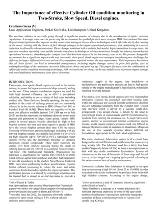
  • 7. Figure 6 - Output from System1 showing increased levels of wear. At point A on the graph, the vessel’s engine was started using MGO19 . The sharp rise in wear is typically observed on engine start up and rapidly falls as a film of cylinder oil is formed on the internal surfaces of the liner and piston rings. At Point B, the vessel engine was switched to HFO and, almost instantaneously, the wear levels across all cylinders can be seen to rise to significant levels (>450 PPM) and remain high for a prolonged period of time, not falling rapidly as per at start up, point C. In order to verify the results observed, the operator switched the vessels engine back to MGO in order to check if the recorded wear event was due to the fuel changeover. To verify the results, the operating loads applied to the engine were also kept constant. Increases in wear can be seen during these occurrences, but once switched over to MGO the same rapid decay in wear back down to <50 PPM levels can be seen after such event. To ensure that the results previously observed were correct, the vessel was then switched back to HFO at point D. The same increased wear levels trends are the seen immediately as previously in the graph linking the wear event to the use of the HFO. Further investigations on the vessel were carried out on the fuel system and high levels of cat fines were found on one of the day tanks, possibly due to a fuel oil purifier malfunction. It was also found that the last chance filter elements on the fuel line were of an incorrect specification (32 µm rather than the specified 10 µm). These filters would eventually have minimised the severity of the wear events in the case of off- specification fuel was burned. Once the fuel supply was changed over to another HFO day tank the wear event recorded in the graph in point D rapidly disappeared showing an acceptable liner wear rate. Following the information provided by the real time data supplied by system 1 the crew was also able to track down the incorrect filter and replace it with a correctly specified one. If the wear levels on the cylinders had not been monitored with this online system, continued operation of the engine would have caused a rapid deterioration of the liners across all 6 cylinders. The cost of replacement is typically around USD $40000 per liner. This unexpected expenditure coupled with the associated overhaul downtime was thus avoided and no off-hire of the vessel occurred, saving the operator significant expenses, inconvenience and loss of reputation. CONCLUSIONS In this paper, the results of both on-board off-line and on-line analysis of scrapedown oil have been presented with field data obtained from seagoing vessels. The data shown demonstrates that the on-shore scrapedown oil analysis can be used in conjunctions with on-board offline and online condition monitoring solutions. The combination of these different techniques shown to provide a great wealth of information, allowing ship owners and operators to take immediate corrective actions to mitigate any damage, to allow continued, efficient operation and prevented the high costs associated to undetected liner wear events. The savings associated with this early warnings in both presented cases far outweighed the cost of the condition monitoring tools used to detect them. The prevention of liner damage to a 6 cylinder two stroke slow speed diesel engine as a result of data provided by the System 1, just 3 days after it was installed, convinced the ship owner of the high value of the provided data. The above shown case actually convinced the shipping company management to roll out the system across the remaining vessels of the fleet. ACKNOWLEDGMENTS. Dr. Steve Dye contributed heavily to the writing of this paper and his work is acknowledged. We are indebted to Dr Stuart Lunt for the help provided in proofreading this document. 19 MGO: Marine Gas Oil. Distillate fuel roughly equivalent to a No. 2 fuel oil.
  • 8. Appendix A – Full ferrous wear measurements. Test No. SO15- 01675.001 SO15- 01675.002 SO15- 01675.003 SO15- 01675.004 SO15- 01675.005 SO15- 01675.006 Elemental Analysis by ICP - Iron (ppm) 830 536 595 752 809 373 Model1 FW v0.04 1 1845 540 445 965 830 310 2 1850 545 445 965 840 310 3 1850 545 450 965 840 310 Average 1848.33 543.33 446.67 965.00 836.67 310.00 GOLD Model1 (CAL035) 1 1887 461 473 854 814 288 2 1902 464 478 859 814 291 3 1915 467 480 861 814 292 Average 1901.33 464.00 477.00 858.00 814.00 290.33 Gold Model2 (CAL157) 1 1784 429 414 764 736 275 2 1801 432 421 754 739 275 3 1812 437 419 761 746 277 Average 1799.00 432.67 418.00 759.67 740.33 275.67
  • 9. Appendix B – CCTK Results Oil sample from cylinder 1 Oil sample from cylinder 2 Oil sample from cylinder 3 Oil sample from cylinder 4
  • 10. Oil sample from cylinder 5 Oil sample from cylinder 6 Comparator Scaled 20-400 ppm Iron concentration disk