Regression analysis: Simple Linear Regression Multiple Linear Regression
Sound Devices 788T
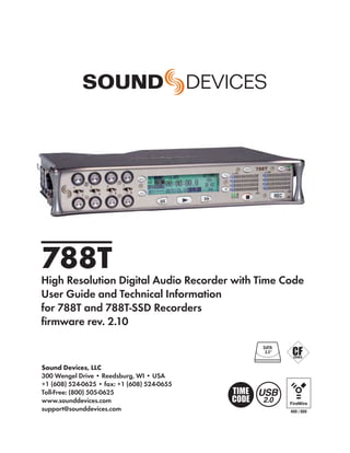
1. 788T
High Resolution Digital Audio Recorder with Time Code
User Guide and Technical Information
for 788T and 788T-SSD Recorders
firmware rev. 2.10
SATA
2.5"
UDMA
Sound Devices, LLC
300 Wengel Drive • Reedsburg, WI • USA
+1 (608) 524-0625 • fax: +1 (608) 524-0655
Toll-Free: (800) 505-0625 USB
www.sounddevices.com 2.0
support@sounddevices.com 400 / 800
2. Table of Contents
Quick Start Guide . . . . . . . . . . . . . . . . . . . . . . .4 Sample Rate Converters
Front Panel Descriptions . . . . . . . . . . . . . . . .10 Word Clock Input
Video Sync
Panel Lock
Digital Inputs 1-2, 3-4, 5-6, 7-8
Left Panel Connectors and Controls . . . . . .13 Multi-Unit Linking Via C. Link
Right Panel Connectors and Controls . . . . .14 Outputs – Analog and Digital . . . . . . . . . . . .46
Rear Panel Descriptions . . . . . . . . . . . . . . . .15 Output Types
LCD Display Descriptions . . . . . . . . . . . . . . .16 Analog Balanced Line Outputs 1-4
Analog Unbalanced Output 5-6
Input Settings Window Descriptions . . . . . .19 Balanced Digital AES Outputs 1-6
Track Setup Window . . . . . . . . . . . . . . . . . . . .21 Headphone Output . . . . . . . . . . . . . . . . . . . . .47
Track Level Meters View Selecting Headphone Sources
Track Routing View Setting Headphone Source Options
Track-to-Media View Headphone Source as Outputs
Master Gain Levels View Input Solo (PFL)
Take List Descriptions . . . . . . . . . . . . . . . . . .24 MS Stereo Monitoring
Drive Directory (File Viewer) Descriptors . . .26 SoundField B-Format Surround Monitoring
Root Directory Multi-Function Rotary Switch Behavior
Input Setup and Control . . . . . . . . . . . . . . . . .28 Headphone Favorite Selection
Input Trim and Input Faders Headphone Playback Mode
Input Settings Window Headphone Warning Tones
Input Type Recording Start and Stop Bells
Phantom Power Low Battery Warning
High-Pass Filters Headphone Power Up Gain
Input Gain CL-9 Headphone Monitoring
Input Limiters Metering and Display . . . . . . . . . . . . . . . . . . .51
Input Polarity Output Meter
Input Mute Meter Scale
Input to Track Routing Favorite Meter Mode
Analog Inputs Digital Meter View
Input Linking (Stereo or MS Decoding) Meter Ballistics
Digital Inputs VU (Volume Units)
AES42 Digital Microphones Peak Only
Input Delay Peak/VU
Deactivate Inputs Peak Hold Time
Input to Track Routing . . . . . . . . . . . . . . . . . .33 Input Activity Ring LEDs
Pre-Fade vs. Post Fade Headphone Peak LED
Routing Using the Input Settings Window Tone Oscillator
Routing Using the Setup Menu LCD Contrast & LED Brightness
Routing Using The Track Setup Window LCD Backlight
Routing Using the CL-8 CL-2 Metering and Display
Routing Using the CL-9 CL-8 Metering and Display
CL-9 Metering and Display
Track Arming . . . . . . . . . . . . . . . . . . . . . . . . . .37
Wave Agent Metering and Display
Track Enabling Using the CL-9
Track Status Indication Time Code . . . . . . . . . . . . . . . . . . . . . . . . . . . .56
Track-to-Media Routing Frame Rate
Master Gain Levels F Sampling Rate Modes
Track Limiters 48.048k and 48.048kF
Master Gain Levels Using the CL-9 Fostex DV40
47.952k and 47.952kF
Sampling Rate and Bit Depth . . . . . . . . . . . . .40 96.096k and 96.096kF
Sampling Rate Time Code Modes
Sampling Frequency and Audio Bandwidth Off
Bit Depth Free Run:
Bit Depth and Dynamic Range Record Run
Synchronization . . . . . . . . . . . . . . . . . . . . . . .41 Free Run Jam Once
Clock Master 24 Hour Run
Word Out Ext TC
AES Digital Outputs Ext TC/cont
Clock Slave Ext TC-Auto Record
Ext TC/cont-Auto Record
Internal
3. 788T/788T-SSD User Guide and Technical Information
Time Code Hold Off Storage Media – Internal Drive . . . . . . . . . . .82
Jam Menu 788T Drive Type
Jam RX TC 788T-SSD Drive Type
Jam Zeros Drive Replacement
Jam Value
Edit Value
Storage Medium – Removable CompactFlash 84
User Bits When to Use CF
NTSC Standard Def Video Production Formatting
Speed Testing
Recording . . . . . . . . . . . . . . . . . . . . . . . . . . . .62 Qualified CF Cards
Recording
Pre-Record Buffer Storage Medium – External FireWire Drives .85
Media Select When to Use External FireWire Drives
Failure During Recording Formatting
Record Timer FireWire Bus Powering
Qualified Drives
Playback . . . . . . . . . . . . . . . . . . . . . . . . . . . . .64 DVD-RAM Drives
AutoPlay
File Copying Among Available Media . . . . . .86
Audio File Formats . . . . . . . . . . . . . . . . . . . . .64 Copying Individual Files
.WAV Error Conditions:
File Type
Monophonic
File Transfer to Computer . . . . . . . . . . . . . . .88
Polyphonic Powering . . . . . . . . . . . . . . . . . . . . . . . . . . . . .89
Take Management . . . . . . . . . . . . . . . . . . . . . .65 Lithium Ion Rechargeable Battery
Scene Name/Numbering External Powering and Battery Charging
Scene Name Incrementing/Decrementing Time Code Clock Battery
Take Numbers Auto Functions with External Powering
Take Number Incrementing/Decrementing Power Consumption Variables
False Take Control Firmware Upgrades . . . . . . . . . . . . . . . . . . . .92
Emptying the False Take Folders Version Information
Track Naming Upgrading Firmware
Take List . . . . . . . . . . . . . . . . . . . . . . . . . . . . .70 Remote Control . . . . . . . . . . . . . . . . . . . . . . . .94
Refresh Take Metadata Keyboard Assignments
Take Edit Menu Menu Keys
Notes String Edits & Take Name/Number (Renaming & Notes)
Renaming Takes Assignable Shortcuts
Duplicate Takes Shortcut List Functionality
Circle Take Logic In
Project Logic Out (Record Tally)
Scene CL-1 Keyboard and Remote Control Interface (optional) 97
Take Connecting the CL-1
Tape (Roll) CL-1 Keyboard Interface
Set and Clear Copy Flags CL-1 Logic Inputs and Outputs
Deleting Takes Logic Inputs
Renaming Tracks Logic Outputs
Wave Agent Metadata Entry and Editing
CL-2 Remote Fader (optional) . . . . . . . . . . . .99
Wave Agent Beta . . . . . . . . . . . . . . . . . . . . . . .75 CL-2 Connection
File Management . . . . . . . . . . . . . . . . . . . . . .75 Connecting the CL-2
Automatic File Splitting CL-2 Panel Descriptions
File Time and Date Fader Assignment
Folder Actions CL-2 Switches
The Drive Directory (File Viewer) . . . . . . . . . .77 CL-8 Controller (optional) . . . . . . . . . . . . . . .103
Navigation CL-8 Connection
Selecting Files for Playback CL-8 Front Panel Descriptors
Folder Options Menu CL-8 Side Panel Descriptors
Rename Folders CL-8 Back Panel Descriptors
Set and Clear Copy Flags CL-8 Fader Control
Delete Folders CL-8 Views
Drive Directory Options Menu Main View
Set and Clear Copy Flags Aux Routing View
Emptying the Trash Input Settings View
Erase (Media Format) Slate Mic
1
4. 788T/788T-SSD User Guide and Technical Information
Table of Contents cont.
Slate Mic Routing Wave Agent Control . . . . . . . . . . . . . . . . . . .127
Slate Mic Level
Setup Menu . . . . . . . . . . . . . . . . . . . . . . . . . .128
CL-9 Linear Fader Controller (optional). . . .109 User Setup Data File
CL-9 Connection Setup Menu Shortcuts
CL-9 Rear Panel Descriptors
Front Panel Button Shortcuts . . . . . . . . . . .137
CL-9 Fader Control
CL-9 Master Gain Level Controls Connector Pin Assignments . . . . . . . . . . . .138
CL-9 Headphone Monitor Specifications . . . . . . . . . . . . . . . . . . . . . . . .139
Headphone Level Appendix A - Recording Time Calculation .141
Monitor Selection Uncompressed Recording Time in Track-Hours
Setup Menu Navigation From CL-9 Record Time
Soloing Inputs. Outputs, or Tracks PCM Audio
EQ Audio Data Rate = Bit Depth x Sampling Frequency
Pan Appendix B – Metadata Implementation . . .142
Factory Modes
User Modes (U1-U4) Appendix C – File Naming . . . . . . . . . . . . . .143
CL-9 Input-to-Track Routing Monophonic WAV File Track Number Designators
CL-9 Communications Duplicate File Names
Slate Appendix D- FAT32 and Maximum File Size 144
Tone Oscillator Appendix E - Accessories . . . . . . . . . . . . . .145
Returns
COMs 788T CE Declaration of Conformity . . . . . .147
Setting up a Bidirectional Talk Back Circuit Software License . . . . . . . . . . . . . . . . . . . . .148
CL-9 Transport Control Warranty and Technical Support . . . . . . . . .149
CL-9 Footswitch
CL-9 LED Brightness
CL-9 Specifications
2
v. 2.10 Features and specifications are subject to change. Visit www.sounddevices.com for the latest documentation.
5. 788T/788T-SSD User Guide and Technical Information
Welcome
Thank you for purchasing the 788T/788T-SSD. The ultra-compact 788T records and plays back audio
to and from its internal drive, CompactFlash, or external drives, making field recording simple and
fast. It writes and reads uncompressed PCM audio at 16 or 24 bits with sampling rates between 32
kHz and 96.096 kHz. The time code implementation makes the 788T ready for any recording job—
from over-the-shoulder to cart-based production.
The 788T implements a no-compromise audio path that includes Sound Devices’ high-performance
microphone preamplifiers. Designed specifically for high bandwidth, high bit rate digital recording,
these preamps set a new standard for frequency response linearity, low distortion performance, and
low noise.
With documentary and ENG mixing engineers in mind, the 788T is very small, while still being
feature-rich. No other recorder on the market matches its size and feature set. In addition, its learn-
ing curve is quite short—powerful does not mean complicated.
Sound Devices took advantage of the best in professional and consumer electronic technologies to
bring incredible feature depth with ease of use. Hard drives and CompactFlash are highly reliable,
industry standard, and easily obtainable. With the ability to write to an external drive, low-cost, por-
table media can be delivered to post production. The removable, rechargeable battery is a standard
Sony-compatible Li-ion camcorder battery pack. The 788T interconnects with Windows and Mac OS
computers for convenient data transfer and backup.
The 788T is available in two models, The standard 788T ships with an internal hard drive. The 788T-
SSD ships with an internal solid state drive. Throughout this document both models will be referred
to as the 788T., except when information is specific to each model.
788T and 788T-SSD Firmware Known Issues
For a complete list of any known issues: www.sounddevices.com/download/788t-firmware.htm.
Copyright Notice and Release
All rights reserved. No part of this publication may be reproduced, stored in a retrieval system, or transmitted in any form or by any
means, electronic, mechanical, photocopying, recording, or otherwise, without the expressed written permission of SOUND DEVICES,
LLC. SOUND DEVICES is not responsible for any use of this information.
SOUND DEVICES, LLC shall not be liable to the purchaser of this product or third parties for damages, losses, costs, or expenses
incurred by purchaser or third parties as a result of: accident, misuse, or abuse of this product or unauthorized modifications, repairs, or
alterations to this product, or failure to strictly comply with SOUND DEVICES, LLC’s operating and installation instructions.
Microsoft Windows is a registered trademark of Microsoft Corporation. Macintosh is a registered trademark of Apple Computer. Other
product and company names mentioned herein may be the trademarks of their respective owners.
The sound waves logo is a registered trademark of Sound Devices, LLC.
3
6. 788T/788T-SSD User Guide and Technical Information
Quick Start Guide
This Quick Start Guide provides a brief overview for first use of the 788T/788T-SSD. For detailed operating
instructions refer to the 788T/788T-SSD User Guide and Technical Information.
1) Connect Power.
Connect the supplied AC-to-DC power supply to the DC connector on the Right
Panel.
2) Attach the supplied Li-ion rechargeable battery to the recorder.
Be certain to line up the battery contacts with the battery compartment mounting
pins. Rotate the battery lock to secure the battery in place.
Included L-Mount Battery
788T Rear Panel
The included battery must be charged for six hours prior to initial use.
The 788T will charge the L-Mount battery when DC is connected.
3) Connect analog microphone or line sources.
Quickstart
Please refer to the 788T/788T-SSD User Guide and Technical Information for con-
nections with digital audio sources.
788T Left Panel
4) Connect headphones
Connect to either the 1/4-inch or 1/8-inch headphone output on the Right Panel.
WORD / VID IN
DC IN
10-18V
MENU
SELECT 1 2
ANALOG BAL LINE OUTS
3
FW800
BAL AES
FW400 USB
SYNC
788T Right Panel
OUT
PIN 4 (+)
PIN 1 (-)
UNBAL 5,6 4 1,2 3,4 WORD OUT
TIMECODE
4
v. 2.10 Features and specifications are subject to change. Visit www.sounddevices.com for the latest documentation.
7. 788T/788T-SSD User Guide and Technical Information
5) Press and hold the PWR key for one second to power on.
UT
788T PWR
ARM
C
D
E
F
0 0
dBFS dBFS
REC
6) INPUTS MUST BE ACTIVE TO BE RECORDED.
Press in to release recessed Input Gain Controls. Rotate the knob clockwise past the
detent to turn on the input.
In the full counter-clockwise position, the input is not active and is not available for use.
Quickstart
7) Access the Input Settings Window
To access, momentarily move the Input Selector Switch in the direction of the Input.
This action also sends the input signal to the headphone monitor.
1 3 5 7
MENU
1 Left for odd inputs
2 4 6 8 HDD
2 Right for even inputs
Input Setting Options:
Source (mic/line/digital)
Phantom (on/off)
MENU
High-Pass Filter (on/off)
Limiter (on/off)
HDD
Input-to-Track Routing
Mute (none / mute)
Polarity (normal / reverse)
5
8. 788T/788T-SSD User Guide and Technical Information
Press adjacent key to change the parameter.
8) The Input Settings Window is where changes are made to input parameters.
For example, press the TONE key to toggle Phantom Power on and off. Turn the
Multi-Function Rotary Switch to adjust the High-Pass Filter Frequency.
Turn the Multi-Function Rotary Switch
MENU
HDD
9) INPUTS MUST BE ROUTED TO TRACKS FOR RECORDING.
From the Input Settings Window, press the PLAY key to enter Input-to-Track Rout-
ing. Inputs can be assigned to any Track. The Rewind and Fast-Forward keys route
inputs to Track L and R, respectively. Turn the Multi-Function Rotary Switch to
move among Tracks A - X2. Push in on the rotary switch to route the input to the
track. Refer to the 788T User Guide for details on pre- and post-fade routing. Press
PLAY again to return to the Input Settings Window.
Quickstart
MENU MENU
HDD HDD
Press PLAY to enter Press REW to route to
Input-to-Track routing. Track L, Press FF to
Press again to exit. route to Track R. Use the
Multi-Function Rotary
Switch to route to Tracks
A - X2.
10) Return to the Main Display.
Momentarily move the Input Selector Switch again.
11) Press the MENU key to enter the Setup Menu.
The Setup Menu allows you to configure various options, including Sampling Rate,
Bit Depth, Time Code, etc. Navigate through the Setup Menu by turning the Multi-
Function Rotary Encoder. Refer to the 788T/788T-SSD User Guide for Setup Menu
details.
MENU
R
L
A
HDD
B
6
v. 2.10 Features and specifications are subject to change. Visit www.sounddevices.com for the latest documentation.
9. 788T/788T-SSD User Guide and Technical Information
Setup Menu Basics:
Highlighted selection
MENU
Selects highlighted option
Navigates through the menu
HDD
Exits option and menu
Cancels changes and exits the menu
Turn the Multi-Function Rotary Switch to navigate
through the Setup Menu, push to select an option.
12) A TRACK MUST BE ENABLED TO BE RECORDED.
Press the INPUT key to enter the Track Setup Window, where Tracks are enabled
for recording. An * (asterisk) next to a Track indicates that the track is record en-
abled. Navigate through the Tracks using the Multifunction Rotary Switch. To en-
able/disable the track, press in on the Multi Function Rotary Switch. Track Status is
indicated by the asterisk and by the blue Track Status LEDs on the 788T front panel.
When the LED and asterisk is solid the track is armed and will be recorded, if they
are flashing the track is enabled but no active input is routed to it and will not be
recorded, if the asterisk and LED are off the track is disabled.
Quickstart
INPUT
788T PWR
ARM ARM
R C
L D
A E
B F
0 0
dBFS dBFS
IN CF EX REC
Track Setup Menu Basics:
Selector Box
MENU
Track Status Indicator
Input Routing Window
HDD
Master Levels Window
Track-to-Media Window
VU1 / VU2 Toggle
VU1 / VU2 toggle selects the Tracks displayed on the right-hand column of Track Meter LEDs.
VU1 = Tracks C, D, E, F, G. VU2 = G, H, X1, X2.
Tip: After Inputs are routed to Tracks and the Tracks are record enabled, simply click the Input Gain Pots on and
off to arm and disarm tracks respectively.
7
10. 788T/788T-SSD User Guide and Technical Information
13) HEADPHONE MONITOR.
Press the STOP key to return to the Main Display. Turn the Multi-Function Rotary
Switch to select the headphone preset best suited for the particular setup.
Active headphone routing. Track L in the left ear, Track R in the right ear.
14) Press the REC key to start recording.
Press the STOP key to stop the recording. Press the PLAY key to playback the last
recorded take.
15) Press the HDD key to enter the Take List.
The take list displays a listing of all recordings.
MENU
R
L
A
HDD
B
Quickstart
Take List Basics:
Next Take
MENU
Selected Take (*= Last recorded Take)
Rename Take
HDD
Metadata Edit Menu
Add Take Notes
Exits the Take List
Turn the Multi-Function Rotary Switch to navigate through the Take List,
push to toggle the type of information displayed.
16) From the Take List, press the HDD key again to enter the Drive Directory.
8
v. 2.10 Features and specifications are subject to change. Visit www.sounddevices.com for the latest documentation.
11. 788T/788T-SSD User Guide and Technical Information
Drive Directory Basics:
File Information Toggle
Jump to Root Directory
MENU
Selected File
Return to Take List
HDD
Exits the Drive Directory
Drive Formatting and other media-specific operations are accessed in the
Drive Options Menu located at the root directory.
17) After recording, transfer files from the 788T to a computer using either
FireWire 400, FireWire 800, or USB.
When connecting to a computer with a USB cable, make sure that the Setup Menu
option FireWire/USB: Connection is set to Connect as Mass Storage.
WORD / VID IN WORD / VID IN
WORD / VID IN
DC IN DC IN
DC IN
10-18V 10-18V
MENU 10-18V MENU
MENU
SELECT 1 2 3 SELECT 1 2 3 SELECT 1 2 3
FW800 FW400 USB FW800 FW400 USB
ANALOG BAL LINE OUTS SYNC ANALOG BAL LINE OUTS FW800 FW400 USB
SYNC ANALOG BAL LINE OUTS SYNC
BAL AES BAL AES
OUT BAL AES OUT
OUT
PIN 4 (+) PIN 4 (+)
PIN 4 (+)
PIN 1 (-) PIN 1 (-)
PIN 1 (-)
UNBAL 5,6 4 1,2 3,4 WORD OUT UNBAL 5,6 4 1,2 3,4 WORD OUT
TIMECODE UNBAL 5,6 4 1,2 3,4 WORD OUT TIMECODE
TIMECODE
Quickstart
FireWire 800 FireWire 400 USB
FW800
USB
FW400
To avoid any possible directory corruption on the 788T, do not interrupt the connection process and always prop-
erly dismount the drives from the operating system. On Mac OS platforms, drag the drive icons to the trash. On
Windows platforms, use the “Disconnect External Media” icon in the system tray.
18) Press and hold the PWR key for one second to shut down the recorder.
UT
788T PWR
ARM
C
D
E
F
0 0
dBFS dBFS
REC
9
12. 788T/788T-SSD User Guide and Technical Information
Front Panel Descriptions
All 788T settings can be accessed and monitored through the front panel LCD and navigation keys.
This allows the unit to be placed in a production bag along with field mixers and wireless transmit-
ters and receivers.
1 2 3 4 5 6 7 8 9 10 11 12
INPUT
788T PWR
ARM ARM
MENU
R C
1 3 5 7 L D
A E
2 4 6 8 HDD
B F
0 0
dBFS dBFS
IN CF EX REC
13 14 15 16 17 18 19 20 21
1) Input Activity Ring LEDs 4) MENU Key
The LEDs surrounding the Input gain Accesses the 788T Setup Menu. When
pots indicate the input activity for each in the Setup Menu use the MENU key
input, respectively. The LEDs illuminate to move up through the options and
in various colors and intensities to repre- parameters.
sent the state of each input.
See Metering and Display. 5) LCD Display
Primary display of 788T status. The
2) Input Gain Control LCD is backlit by pressing and holding
By default, controls the analog and digi- the LCD backlight key and pressing the
tal input gain (input trim) of each chan- Multifunction Rotary Switch. When the
nel respectively. The Input gain control backlight is active the backlight color
can be changed in the Setup Menu to act can be set to indicate the recorder’s
as fader controls. See Fader Control. current mode. Red = Recording Mode,
Input Gain Pots can be switched to the Green = Playback Mode, White =
Off position to deactivate the input. Standby Mode
Deactivated inputs are muted and un-
routed from any designated track. This 6) TONE key
ultimately extends battery life. See Input Press to activate the tone oscillator, press
Setup and Control and hold for two seconds or longer to
latch on, press again to deactivate. Fre-
3) Input Selector/Solo Switch quency, tone level, and routing are con-
Selects odd numbered inputs when trolled in the Setup Menu. When in the
pushed left and even numbered inputs Setup Menu use the TONE key to enter
when pushed right. Selecting an input Setup Menu options and select parame-
using the Input Selector/Solo Switch ters when the check mark appears in the
will display the respective Input Settings upper right hand corner of the LCD.
Window. If enabled in the Setup Menu,
the Input Selector Switch will also PFL 7) Track Status LEDs
(pre fade listen) the input in the head- A solid blue LED indicates that the
phone monitor. To exit the Input Settings respective track is armed and ready to
Window, press the Input Selector Switch record. Armed tracks are both record
again or select another Input. For mo- enabled in the Track Setup Window and
mentary action, press and hold the Input have at least one active input routed to
Selector in position for one second or it. The LED flashes blue when the Track
longer. See Input Setup and Control is enabled but there is no active input
routed to it and will not be recorded.
The LED is off when the track is dis-
abled.
10
v. 2.10 Features and specifications are subject to change. Visit www.sounddevices.com for the latest documentation.
13. 788T/788T-SSD User Guide and Technical Information
8) Level Meter LEDs 14) Rewind Key
Eight, 13-segment track level-meters in- Performs reverse (REW) scrubbing
dicate level in dBFS. Metering scale, bal- through the played file when pressed in
listics, and peak hold times are selected playback and play-pause mode. Play-
in the Setup Menu. Tracks C, D, E, F can pause indicated by flashing A-time on
be used to view Tracks G, H, X1, X2. See LCD. Reverse playback rate increases
Metering and Display. the longer the key is held. In play-stop
mode (indicated by flashing filename
9) INPUT Key on LCD) selects the previous file in the
Press to access the Track Setup Menu, record folder (either daily folder or main
from which the user can arm/disarm folder).
record tracks and view meter activity for
all 12 tracks. Press and hold the STOP 15) Play Key
key then press the Input key to access Plays back the file displayed in the LCD.
the Input: Track Routing Setup Menu. If pressed immediately after recording is
Cycle through factory and custom rout- stopped, the most recently recorded file
ings by pressing the Input key while is played back.
holding the STOP key. See Input-to-Track
Routing 16) Fast-Forward Key
Performs fast-forward (FF) scrubbing
10) Power Key through the played file when pressed in
To power up the unit, press and hold the playback and play-pause mode. Play-
Power (PWR) Key for about one second. pause indicated by flashing A-time on
To power the unit down, press and hold LCD. Fast forward rate increases the lon-
the Power Key for about one second. ger the key is held. In play-stop mode
(indicated by flashing filename on LCD)
11) Power/Charge LED selects the next file in the record folder
Indicates the 788T is powered and avail- (either daily folder or main folder).
able for operation. Indicates the charge
status of the onboard battery charger. 17) LCD Backlight Key
Press to toggle the Level Meter LEDs
12) Headphone Output Peak LED View 1 (Tracks C - F) and View 2 (Tracks
Indicates overload of the headphone G, H, X1, X2). Press and hold for 2 sec-
amplifier. When lit, the headphone cir- onds to toggle between the select meter
cuit is overloading. Reduce headphone scale and the favorite meter scale. See
level. Metering. Hold the Backlight key then
press the Multifunction Rotary Switch to
13) HDD Key toggle the LCD and Front Panel soft key
Press to enter the Take List and Drive backlighting on and off. Hold the Back-
Directory. From the Take List, view and light key and turn the Multi-Function
edit metadata across all storage medi- Rotary Switch to adjust the brightness
ums. From the Drive Directory navigate of LEDs. In the Setup Menu the LCD
between storage media, folders, and Backlight key functions as the cancel
files. View folder and file properties and and exit key.
select files for playback.
The media that is selected for playback
is shown on the left hand side of the
main screen. Press and hold the HDD
key to toggle between available media.
If only one media is present, media
toggle is disabled. When in the Setup
Menu use the HDD key to move down
through the options and parameters.
11
14. 788T/788T-SSD User Guide and Technical Information
Front Panel Descriptions cont.
1 2 3 4 5 6 7 8 9 10 11 12
INPUT
788T PWR
ARM ARM
MENU
R C
1 3 5 7 L D
A E
2 4 6 8 HDD
B F
0 0
dBFS dBFS
IN CF EX REC
13 14 15 16 17 18 19 20 21
18) Media Activity LEDs 20) Record Key
Indicates storage media activity. IN Press to begin recording. The 788T is
(internal drive), CF (CompactFlash), a record-priority device; pressing this
EX (external FireWire device). The LED key starts recording and discontinues
illuminates green when the storage all other functions, except file opera-
media is ready, illuminates yellow when tions. The REC key will illuminate red
the storage media is writing/reading when the 788T is actively recording. If
and while connected to a computer, and the selected storage media is not ready
illuminates red when the storage media to begin recording a new file, the REC
has encountered an error or if the drive key will flash red until the recording has
has less than one minute of recording begun. Pressing the REC key during re-
time left. cording can set a cue marker, start a new
file, as selected in the Setup Menu.
19) Stop/Pause Key
Momentarily press and hold this key to 21) Record LED
stop recording. In playback mode, a sin- Illuminates red when record mode is
gle press pauses playback (play-pause), active.
allowing audio scrubbing with the FF
and REW keys. Another press of the key
enters play-stop mode where the FF and
REW keys select files for playback from
the current directory, the filename and
time display flash to indicate that a new
file has been selected. One more press of
the key exits playback mode.
Pressing the STOP key whilst in stop
mode displays the name of the next file
to be recorded in the LCD. In the Setup
Menu the STOP key is also used to exit
from any menu, returning to the main
display.
12
v. 2.10 Features and specifications are subject to change. Visit www.sounddevices.com for the latest documentation.
15. 788T/788T-SSD User Guide and Technical Information
Panel Lock
Press and hold the LCD backlight key then the TONE key to bring up the front panel But-
ton Lock Screen. Button lock prevents unintentional setting changes and/or record status. The 788T
displays any button lock options currently enabled.
select the soft keys to
activate the appropriate
button lock mode
There are three modes:
• Unlocked – all keys are accessible and operate normally.
• Non-Transport Lock – All front panel controls are locked except the Record, Stop, Play, Rewind
and Fast Forward keys.
• Lock All – All front panel keys are locked except the REC key. The REC key is kept active so
the user can initiate recording after entering this mode and enter cue markers. To stop record-
ing in this mode, you must disengage the panel lock and press the stop key.
Left Panel Connectors and Controls
1 2 3
1) XLR Analog Inputs Channels 1-4 3) Headphone Volume
Active-balanced analog microphone- or Adjusts the headphone volume. NOTE:
line-level input for inputs 1-4 on XLR the 788T is capable of producing ear-
connector. Input type is set within the damaging levels in headphones. Please
Input Settings Window. Pin-1 ground, use with caution
pin-2 (+), pin-3 (−).
2) TA3 Analog Input Channels 5-8
Active-balanced analog microphone-
or-line-level input connector for inputs
5-8. Input type is set within the Input
Settings Window. Pin-1 ground, pin-2
(+), pin-3 (−).
13
16. 788T/788T-SSD User Guide and Technical Information
Right Panel Connectors and Controls
1 2 3 4 5 6 7
WORD / VID IN
DC IN
10-18V
MENU
SELECT 1 2 3
FW800 FW400 USB
ANALOG BAL LINE OUTS SYNC
BAL AES
OUT
PIN 4 (+)
PIN 1 (-)
UNBAL 5,6 4 1,2 3,4 WORD OUT
TIMECODE
8 9 10 11 12
1) Multi-Function Rotary Switch 6) Sync Input
When in the Setup Menu, the rotary This BNC is used to connect an exter-
switch moves between menu selections; nal video sync or word clock reference
push to enter selection or enter data. signal for word clock purposes. Accepts
In Record and Playback modes, selects NTSC, PAL, and Tri-level video syncs as
headphone monitor source; press action well as word clock rates between 32 kHz
is user selectable. Turn the knob while and 48.048 kHz.
holding the LCD Backlight key to adjust
the brightness of LEDs. 7) External DC In
Accepts power from 10–18 volts DC to
2) TA3 Analog Outputs 1-4 power and charge the Li-ion battery.
Active-balanced, analog outputs 1-4. Hirose 4-pin connector is wired pin-1
Program source and attenuation lev- negative (-), pin-4 positive (+). Pin-2 and
els are user selectable. Pin-1 ground, pin-3 are not connected. Charging char-
pin-2 (+), pin-3 (–). When connecting acteristics are set in the Setup Menu.
to an unbalanced input, do not connect
pin-3. 8) Headphone Output
1/4-inch and 3.5 mm TRS stereo head-
3) FireWire 800 (IEEE-1394b) Port phone connectors. Can drive head-
Connection to a computer (Mac OS, phones from 8 to 1000 ohm impedances
Windows) to access the internal hard to very high levels. Tip = left, ring =
drive and CompactFlash volumes as right, sleeve = ground.
mass storage devices. Also used to at-
tach external FAT32-formatted FireWire 9) Analog Output 5-6
drives to the 788T for direct recording Unbalanced output on 3.5 mm TRS
and copying. stereo connector. Program source and at-
tenuation levels are user selectable. Tip
4) FireWire 400 (IEEE-1394a) Port = left, ring = right, sleeve = ground.
Connection to a computer (Mac OS,
Windows) to access the internal hard 10) AES3 Output 1-2 and 3-4
drive and CompactFlash volumes as Transformer-balanced AES3 digital out-
mass storage devices. Also used to at- puts 1-2 and 3-4. Program source is user
tach external FAT32-formatted FireWire selectable.
drives to the 788T for direct recording
and copying. 11) Time Code Multi-Pin
Time code input and output on 5-pin
5) USB-B Port LEMO® connector.
Connection to a computer (Mac OS,
Windows) to access the internal hard 12) Word Clock Output
drive and CompactFlash volumes as Provides a word clock output running at
mass storage devices or for extended the sample rate of the 788T.
display and control of the 788T using
Wave Agent. See Wave Agent for details.
14
v. 2.10 Features and specifications are subject to change. Visit www.sounddevices.com for the latest documentation.
17. 788T/788T-SSD User Guide and Technical Information
Rear Panel Descriptions
1 2 3 4
KEYBD OUT C.LINK IN
AES I/O, GPIO, PWR
COMPACT FLASH
5 6
1) USB Keyboard Input 5) Multi-Function DE-15 Connector
USB A Female Connector for USB key- Mates with Sound Devices XL-88 Multi-
board and CL-8 Controller See Remote Pin Breakout Cable. The DE-15 connec-
Control for more details regarding Keyboard tor acts as AES3 Inputs 1-8, AES3 Out-
and CL-8 setup and functionality. puts 5-6, and Logic In and Out. Analog
and digital inputs can be used simulta-
2) C. Link In/Out neously. See Connector Pin Assignments.
RS-232 protocol interface on 6-pin Sample Rate Converters are enabled
modular (“RJ-12”) connector for link- on each AES input when Setup Menu
ing multiple 7-Series recorders together. REC: SYNC SOURCE is set to Internal.
Word clock, machine transport, and time See Sample Rate Converters.
code are carried on the C. Link connec- AES inputs support AES42 Mode 1 oper-
tor. See Multi Unit Linking Via C. Link. ation, supplies +10 V of digital phantom
Also used for connection to CL-1 Key- power. See AES42 Digital Microphones.
board and Remote Control Interface or
CL-2 Remote Fader. See Remote Control 6) Security Slot
for more details. The C. Link In is disabled Compatible with the Kensington® Secu-
when Setup Menu option FireWire/ rity Slot specification. Used to secure the
USB: Connection is set to connect to recorder to a fixed object with a compat-
Wave Agent. ible computer lock.
3) CompactFlash Slot
Accepts CompactFlash media with the
label-side up. Compatible with Type I,
Type II, and MicroDrives. High-speed
UDMA cards are recommended for
higher track count recording.
4) Battery Mount
Accepts Sony® InfoLithium L-Series bat-
teries. Also accepts batteries conforming
to this mount. Numerous capacities,
from 1500 to 7000 mAh are available.
15
18. 788T/788T-SSD User Guide and Technical Information
LCD Display Descriptions
1 2 3 4 5 6 7
8 9 10 11 12 13 14
1) Battery/Voltage Level Indicator 6) Time & Date Display
Indicates voltage level of the remov- Alternating display between the set date
able battery or external power sources. and time of the 788T. This information is
If present, external power overrides written as the creation and modification
battery power. Graphical bar for relative date for generated audio files.
level and numeric indicator for precise
voltage measurement. 7) External Digital Clock Indicator
This display will show when the 788T
2) File Name Display is locked to a valid external sync source,
Shows file name actively being recorded sync reference is user-selectable in the
or played back. In Playback-Stop mode, Setup Menu. The display will indicate
flashing file name indicates that the the current valid sync source
Fast-Forward and Rewind keys can be D = digital input, W = word clock, V =
used to step through files in the current video. The display currently shows that
playback directory. the recorder is successfully locked to a
valid word clock source.
3) Absolute Time (A-time) Display
Shows the elapsed time of the file be- 8) Media Descriptors
ing recorded or played back in hours, For all three media types, an asterisk in
minutes, seconds, and tenths. The A- front of the media descriptor indicates
time and the time code display can be which media is selected for record.
exchanged if a large time code display Highlighted media descriptor indicates
is needed. This display can be set to media selected for record monitoring,
reverse or flash while recording. Flashes playback or file directory display.
in playback-pause mode.
9) Media Status
4) Cue Marker Display (space remaining/record ready)
In Record mode, indicates when cue Bar graph indicates the remaining
markers are set. Markers set by pressing record time available on the select me-
the REC key (option must be selected in dia. Numbers show time in hours and
Setup Menu). In Playback mode, dis- minutes based on the presently selected
plays cue points numerically as they are number of record tracks, sample fre-
reached in a file. quency, and bit rate. Display toggles
between remaining time and track count
5) Sample Rate Indicator when media is set to receive less than
Displays the set record sampling rate. In the full amount of armed tracks. See
Playback mode, displays the currently Track-to-Media Routing. Indicator shows
selected file’s sampling rate. dashes when no media is available or if
there is no armed tracks routed to it.
16
v. 2.10 Features and specifications are subject to change. Visit www.sounddevices.com for the latest documentation.
19. 788T/788T-SSD User Guide and Technical Information
LCD Display Descriptions cont.
1 2 3 4 5 6 7
8 9 10 11 12 13 14
10) Time Code Display 13) Bit Depth Indicator
In Stop and Record modes, displays Shows the set record bit depth. In play-
the time code generated or received by back, shows the file bit depth.
the 788T. In Playback mode, displays
the the time code information of the file 14) Meter Toggle
currently selected for playback (if avail- Press the soft VU (LCD Backlight) key
able). If non-time code files are playing, to toggle between VU1 and VU2 views.
the display shows dashes. The time code VU1 displays Tracks C, D, E, F on the
display can be exchanged with the A- second column of Front Panel Level
time display in the Setup Menu. Meter LEDs, and VU2 displays Tracks G,
H, X1, X2.
11) Headphone Source Display Press and hold the LCD Backlight key
Indicates the source for headphone out- for two seconds to toggle between the
put. Sources and selection order are user selected meter scale and the favorite
selectable in the Setup Menu. meter scale. FAV and the selected VU
view will alternate when favorite meter
12) Time Code Frame Rate mode is active.
Displays the set time code frame rate. If
a file has time code information embed-
ded, the playback frame rate is indi-
cated. If external time code is connected
and the external rate differs from the
rate set internally, the display will flash.
17
20. 788T/788T-SSD User Guide and Technical Information
15
16
17
18
15) Input Level 17) Slate Mic Gain Level (CL-8 only)
When input gain is adjusted, gain level Slate Mic gain level is adjusted from -46
is indicated in dB for the input being to 6 dB in 1 dB increments. To attenuate
adjusted and its neighboring input. The the gain press and hold the CL-8 SLATE
relationship of inputs is configured in button and turn the Multi Function
the following manner and cannot be Rotary Switch.
altered 1,2 / 3,4 / 5,6 / 7,8. Neighboring
inputs are not linked or grouped unless 18) Media Track Count
specifically linked in the Setup Menu. Display toggles between remaining time
Mic input gain range is from 0 dB to 76 and track count when media is set to re-
dB, Line input range is from -25 to 50 dB ceive less than the full amount of armed
and Digital input range is from -25 to tracks. See Track-to-Media Routing.
50 dB.
16) Headphone Gain Level
When the headphone gain is adjusted,
this will appear and indicate the gain
level in dB.
18
v. 2.10 Features and specifications are subject to change. Visit www.sounddevices.com for the latest documentation.
21. 788T/788T-SSD User Guide and Technical Information
Input Settings Window Descriptions
To access the Input Settings Window press the Input Selector Switch into the position of the desired
input. Pushing the Input Selector Switch to the left will select the odd numbered inputs and push-
ing it to the right will select the even numbered inputs. Press the Input Selector Switch for the select
input again to return to the previously displayed screen.
1 2 3 4 5 6
7 8 9 10
1) Input Type 5) High-Pass Filter
The highlighted selection indicates cur- Indicates the state of the High-Pass
rent Input Type. Input Type is select- Filter and the cut off frequency selected.
able from Mic, Line, and Digital Inputs Control the High-Pass Filter by using
for each channel respectively. Toggle the Multi-Function Rotary Switch.
through Input Type selections by press-
ing the MENU key. 6) Phantom Power
The highlighted selection shows the cur-
2) Input Gain Display rent state of phantom power (48 volts)
The Input gain is displayed in dB for for the selected input. Enable or disable
the selected input. Information dis- Phantom Power by using the Tone key.
played toggles between TRIM and
FADER levels when faders are avail- 7) Input Limiter
able. When the Setup Menu option The highlighted selection shows the cur-
INPUT: FRONT PANEL CONTROLS is set rent state of the Input Limiter for the se-
to Fader Controls, use the Multifunction lected Input. Enable or disable the Input
Rotary Switch to attenuate Trim levels. Limiter using the HDD or Rewind key.
Pressing in on the Multifunction Rotary
Switch will toggle control between Trim 8) Input to Track Routing
level and High-Pass Filter control. The highlighted selection(s) indicate the
track(s) the selected input is currently
3) Input Selected routed to. To enter and exit the Input to
Displays the Input that has been se- Track Routing press the Play key.
lected.
9) Input Mute
4) Headphone Monitor Hold Indication When highlighted the select Input is
Press and hold the Input Selector Switch Muted and removed from all tracks.
for five or more seconds to latch Input Input Mute is toggled on and off using
PFL. To exit the PFL monitoring select the Fast Forward key.
another input with the Input Selector
Switch or rotate the Multi-Function 10) Input Polarity
Rotary Switch. This mode only applies When highlighted the current state of
when the INPUT: PFL FUNCTION is set the Input’s Polarity is inversed. Control
to enabled. polarity using the LCD Backlight key.
19
22. 788T/788T-SSD User Guide and Technical Information
The following screen appears if the select Input is linked as a stereo pair.
11
The following screen appears if the select Input gain pot is switched to the Off position.
12
11) Panning Control 12) Channel Is Powered Down
If the Input selected is a linked stereo The Input Settings Window cannot
pair, the odd numbered inputs will dis- be accessed if the Input’s Gain Pot is
play gain and the even numbered inputs switched to Off.
will display the stereo image.
20
v. 2.10 Features and specifications are subject to change. Visit www.sounddevices.com for the latest documentation.
23. 788T/788T-SSD User Guide and Technical Information
Track Setup Window
The Track Setup Window allows a user to record enable or disable tracks, route inputs-to-tracks,
adjust master gain levels, and route tracks-to-media. Press the front panel INPUT key to access the
Track Setup Window. There are four views of the Track Setup Window, Track Level Meters View,
Track Routing View, Master Gain Levels View, and Media-to-Track View. The Track Meters View is
always the first view to appear upon entry of the Track Setup Window. Items that appear in all views
have identical functionality.
Track Level Meters View
1 2
3 4 5 6
1) Track Status Indicator 3) Track Routing View
An * (asterisk) next to a Track indicates Press the Rewind key to access the Track
that the track is record enabled. Navi- Routing View.
gate through the Tracks using the Mul-
tifunction Rotary Switch. The selected 4) Master Gain Levels View
track has a box around it (Track G in Press the Play key to access the Master
the example above).To enable/disable Levels View.
the track, press in on the Multi Function
Rotary Switch. Track Status is indicated 5) Track-to-Media View
by the asterisk and the 788T Front Panel Press the Fast Forward key to access the
Track Status LEDs. When the LED and Track-to-Media view.
asterisk is solid the track is armed and
will be recorded, when it flashes the 6) VU Toggle
track is enabled but no active input is Press the soft VU (LCD Backlight) key
routed to it and will not be recorded, the to toggle between VU1 and VU2 views.
asterisk and LED remain off when the VU1 displays Tracks C, D, E, F on the
track is disabled. second column of Front Panel Level
Meter LEDs, and VU2 displays Tracks G,
2) Track Level Meters H, X1, X2.
Displays all twelve available track Level
Meters. Meter ballistics settings are
identical to the front panel Track Level
Meters and are adjustable within the
Setup Menu.
21
24. 788T/788T-SSD User Guide and Technical Information
Track Routing View
The screen below is the Track Routing View, it appears if the ROUTING (Rewind) Key is selected.
7
8
7) Track Routing 8) Track Level Meters View
Displays all inputs currently routed to Press the Rewind key to return to the
the given track. Rotate the Multi-Func- Track Level Meters Window.
tion Rotary Switch to move the selec-
tor box. Press in on the Multi-Function
Rotary Switch to route an Input to the
Track. Pre- or post-fade routing is ap-
plied as it is defined in the Input Set-
tings Window or the Setup Menu.
Track-to-Media View
The screen below is the Track-to-Media View, it appears if the MEDIA (Fast Forward) Key is selected.
9
10
9) Track-to-Media Routing 10) Track Level Meters View
Displays which media the given track Press the Rewind key to return to the
will be recorded to. Rotate the Multi- Track Level Meters Window.
Function Rotary Switch to move the
selector box. Press in on the Multi-Func-
tion Rotary Switch to toggle the routing
of the track to CompactFlash, Internal
Drive, or External media respectively.
Tracks will only be written to a given
media if it is selected in the Setup Menu
option Rec: Media Select, regardless of
it’s Track-to-Media routing status.
22
v. 2.10 Features and specifications are subject to change. Visit www.sounddevices.com for the latest documentation.
25. 788T/788T-SSD User Guide and Technical Information
Master Gain Levels View
The screen below is the Master Gain Levels View, it appears if the LEVELS (Play) Key is selected.
11 12 13 14
15 16 17 18 19 20
11) L/R Meters 17) Meters
Displays real time metering of Left and Press the soft METERS (Play) key to
Right Track Levels. return to the Track Level Meters View.
12) Track Limiter Indicator 18) AUX Master Gain Level
Appears when Track Limiter is engaged. Displays gain level applied to the Aux
Limiter is active when the indicator is Tracks. Only one bar is displayed when
solid. tracks are linked as a stereo pair. Two
bars are displayed when the tracks are
13) Track Limiter Linked independent (as shown).
Indicates that the track limiter is linked.
19) AUX Master Gain
14) AUX Meters Pressing the soft AUX (Fast Forward)
Displays real time metering of X1 and key will select the Aux Tracks Master
X2 Track Levels. Gain level. Pressing again will select the
track to be controlled. When both tracks
15) L/R Master Gain Level of the pair are highlighted the Tracks are
Displays gain level applied to the Mas- linked as a stereo pair. Gain is adjusted
ter Left and Right Tracks. Only one bar from -60 to +15 dB in .1 dB increments
is displayed when tracks are linked as a using the Multi Function Rotary Switch
stereo pair (as shown). Two bars are dis- or the soft up and down arrows. Press in
played when the tracks are independent. on the Multi Function Rotary Switch to
return to unity gain (0 dB).
16) L/R Master Gain
Pressing the soft L/R (Rewind) key will 20) Limiter Key
select the Left and Right Tracks Master Press the LCD Backlight key to toggle
Gain level. Pressing again will select the the select stereo pairs Track Limiter
track to be controlled. When both tracks status. Each press cycles the various set-
of the pair are highlighted the Tracks tings Off, On, Linked. See Track Limiters
are linked as a stereo pair (as shown). for details.
Gain is adjusted from -60 to +15 dB in .1
dB increments using the Multi Function
Rotary Switch or the soft up and down
arrows. Press in on the Multi Function
Rotary Switch to return to unity gain (0
dB).
23