SlideShare ist ein Scribd-Unternehmen logo
1 von 1
The packet switch consists of k input buffer controllers, k output buffer controllers, and a k x k square
        switch.

A Banyan network is considered for the switching fabric because of its economy, potential VLSI
        implementation, and easiness of routing.


         Each switching element (box) is a 2 X 2 crossbar switch with one buffer on each of its two
         Input links. The packet routing is done by the hardware as follows:

         Each packet has an n-bit header in an n-stage Switch. The switching element (a 2 X 2 crossbar)
         at stage 1 Routes the packet up or down according to the first bit of The header’ (“zero” or
         “one” indicate up or down routing, Respectively) and then removes the first bit from the
         header. The succeeding switching elements will perform the same Routing function by
         removing one bit from the header and Routing the .packet to the next stage until the packet
         Reaches its destination output l I n k. It is easy to see that the Header is simply the binary
         address of the output link at The last stage and is independent of the input link at the First
         stage. If both buffers a t a switching element have a packet and Both packets are going to the
         same output link of the Switching element, then a conflict occurs. In this case, we Assume that
         one of the packets will be chosen, randomly, to go to the next stage and the other one will
         stay in the Buffer. Of course, in order for a packet to be able to move Forward, either the
         buffer at the next stage is empty or There is a packet in the buffer and that packet is able to
         Move forward. Thus, the ability for a packet to move Forward depends o n’ the state of the
         entire portion of the network succeeding the current stage. For simplicity, we can consider
         the switch operating in a clocked format. In the first portion 71 of a clock period T = T~ + r 2
         , control signals. are passed across the network from the last stage toward the first stage, so
         that every packet knows whether it should move forward one stage or stay in the same
         buffer. Then, in the second portion T~ of a clock period T , packets move in accordance with
         control signals and the clock period ends. The whole process repeats in every clock period,
         and packets continue e to be shifted in and out of the switch.

Weitere ähnliche Inhalte

Was ist angesagt?

Error control coding techniques
Error control coding techniquesError control coding techniques
Error control coding techniquesDhanashriNandre
 
Manchester & Differential Manchester encoding scheme
Manchester & Differential Manchester encoding schemeManchester & Differential Manchester encoding scheme
Manchester & Differential Manchester encoding schemeArunabha Saha
 
Presentation Routing algorithm
Presentation Routing algorithmPresentation Routing algorithm
Presentation Routing algorithmBasit Hussain
 
9. parameters of mobile multipath channels
9. parameters of mobile multipath channels9. parameters of mobile multipath channels
9. parameters of mobile multipath channelsJAIGANESH SEKAR
 
The Network Layer
The Network LayerThe Network Layer
The Network Layeradil raja
 
Circuit switching packet switching
Circuit switching  packet  switchingCircuit switching  packet  switching
Circuit switching packet switchingSneha Dalvi
 
Ethernet,token ring
Ethernet,token ring Ethernet,token ring
Ethernet,token ring Hareem Naz
 
Chapter 4 data link layer
Chapter 4 data link layerChapter 4 data link layer
Chapter 4 data link layerNaiyan Noor
 
IEEE 802.11 Architecture and Services
IEEE 802.11 Architecture and ServicesIEEE 802.11 Architecture and Services
IEEE 802.11 Architecture and ServicesSayed Chhattan Shah
 
Flow control and error control techniques in the data link layer protocol
Flow control and error control techniques in the data link layer protocolFlow control and error control techniques in the data link layer protocol
Flow control and error control techniques in the data link layer protocolmdmuaj
 
Sliding window and error control
Sliding window and error controlSliding window and error control
Sliding window and error controlAdil Mehmoood
 
C05 satellite systems
C05 satellite systemsC05 satellite systems
C05 satellite systemsRio Nguyen
 

Was ist angesagt? (20)

Transport layer
Transport layer Transport layer
Transport layer
 
Error control coding techniques
Error control coding techniquesError control coding techniques
Error control coding techniques
 
Manchester & Differential Manchester encoding scheme
Manchester & Differential Manchester encoding schemeManchester & Differential Manchester encoding scheme
Manchester & Differential Manchester encoding scheme
 
go back n protocol
go back n protocolgo back n protocol
go back n protocol
 
Distance vector routing
Distance vector routingDistance vector routing
Distance vector routing
 
Presentation Routing algorithm
Presentation Routing algorithmPresentation Routing algorithm
Presentation Routing algorithm
 
9. parameters of mobile multipath channels
9. parameters of mobile multipath channels9. parameters of mobile multipath channels
9. parameters of mobile multipath channels
 
The Network Layer
The Network LayerThe Network Layer
The Network Layer
 
Circuit Switching
Circuit SwitchingCircuit Switching
Circuit Switching
 
Congestion control
Congestion controlCongestion control
Congestion control
 
Circuit switching packet switching
Circuit switching  packet  switchingCircuit switching  packet  switching
Circuit switching packet switching
 
Ethernet,token ring
Ethernet,token ring Ethernet,token ring
Ethernet,token ring
 
Chapter 4 data link layer
Chapter 4 data link layerChapter 4 data link layer
Chapter 4 data link layer
 
Radio propagation
Radio propagationRadio propagation
Radio propagation
 
IEEE 802.11 Architecture and Services
IEEE 802.11 Architecture and ServicesIEEE 802.11 Architecture and Services
IEEE 802.11 Architecture and Services
 
Flow control and error control techniques in the data link layer protocol
Flow control and error control techniques in the data link layer protocolFlow control and error control techniques in the data link layer protocol
Flow control and error control techniques in the data link layer protocol
 
SDH Principle - Huawei
SDH Principle - HuaweiSDH Principle - Huawei
SDH Principle - Huawei
 
Sliding window and error control
Sliding window and error controlSliding window and error control
Sliding window and error control
 
C05 satellite systems
C05 satellite systemsC05 satellite systems
C05 satellite systems
 
Session Layer
Session LayerSession Layer
Session Layer
 

Andere mochten auch

4b internet protocol
4b internet protocol4b internet protocol
4b internet protocolkavish dani
 
4a logical laddressing
4a logical laddressing4a logical laddressing
4a logical laddressingkavish dani
 
2b switching in networks
2b switching in networks2b switching in networks
2b switching in networkskavish dani
 
4c Address Mapping, Error Reporting and Multicasting
4c Address Mapping, Error Reporting and Multicasting4c Address Mapping, Error Reporting and Multicasting
4c Address Mapping, Error Reporting and Multicastingkavish dani
 

Andere mochten auch (8)

4b internet protocol
4b internet protocol4b internet protocol
4b internet protocol
 
4d routing
4d routing4d routing
4d routing
 
4a logical laddressing
4a logical laddressing4a logical laddressing
4a logical laddressing
 
2b switching in networks
2b switching in networks2b switching in networks
2b switching in networks
 
Chapter 8
Chapter 8Chapter 8
Chapter 8
 
4c Address Mapping, Error Reporting and Multicasting
4c Address Mapping, Error Reporting and Multicasting4c Address Mapping, Error Reporting and Multicasting
4c Address Mapping, Error Reporting and Multicasting
 
circuit switching
circuit  switchingcircuit  switching
circuit switching
 
Switching
SwitchingSwitching
Switching
 

Mehr von Ashu0711

Project ppt
Project pptProject ppt
Project pptAshu0711
 
My cad lab file
My cad lab fileMy cad lab file
My cad lab fileAshu0711
 
My cad file
My cad fileMy cad file
My cad fileAshu0711
 
Monolithic&hybrid ic
Monolithic&hybrid icMonolithic&hybrid ic
Monolithic&hybrid icAshu0711
 
Mini project-report
Mini project-reportMini project-report
Mini project-reportAshu0711
 
Metallization
MetallizationMetallization
MetallizationAshu0711
 
Anti theftsystemforvechicles1 final
Anti theftsystemforvechicles1 finalAnti theftsystemforvechicles1 final
Anti theftsystemforvechicles1 finalAshu0711
 
4.inverter final
4.inverter final4.inverter final
4.inverter finalAshu0711
 
3. solar water heater
3. solar water heater3. solar water heater
3. solar water heaterAshu0711
 
2.avr final
2.avr final2.avr final
2.avr finalAshu0711
 
Industrial training report format
Industrial training report formatIndustrial training report format
Industrial training report formatAshu0711
 
Quality management concepts
Quality management conceptsQuality management concepts
Quality management conceptsAshu0711
 
Project landrover
Project landroverProject landrover
Project landroverAshu0711
 
Ppt land rover
Ppt land roverPpt land rover
Ppt land roverAshu0711
 
Organizational design qm
Organizational design qmOrganizational design qm
Organizational design qmAshu0711
 
Mini p gsm based display
Mini p gsm based displayMini p gsm based display
Mini p gsm based displayAshu0711
 
Mini p gsm based display
Mini p gsm based displayMini p gsm based display
Mini p gsm based displayAshu0711
 
Manufacturing quality qm
Manufacturing quality qmManufacturing quality qm
Manufacturing quality qmAshu0711
 

Mehr von Ashu0711 (20)

Project ppt
Project pptProject ppt
Project ppt
 
Pi q
Pi qPi q
Pi q
 
My cad lab file
My cad lab fileMy cad lab file
My cad lab file
 
My cad file
My cad fileMy cad file
My cad file
 
Monolithic&hybrid ic
Monolithic&hybrid icMonolithic&hybrid ic
Monolithic&hybrid ic
 
Mini project-report
Mini project-reportMini project-report
Mini project-report
 
Metallization
MetallizationMetallization
Metallization
 
Anti theftsystemforvechicles1 final
Anti theftsystemforvechicles1 finalAnti theftsystemforvechicles1 final
Anti theftsystemforvechicles1 final
 
4.inverter final
4.inverter final4.inverter final
4.inverter final
 
3. solar water heater
3. solar water heater3. solar water heater
3. solar water heater
 
2.avr final
2.avr final2.avr final
2.avr final
 
ups
upsups
ups
 
Industrial training report format
Industrial training report formatIndustrial training report format
Industrial training report format
 
Quality management concepts
Quality management conceptsQuality management concepts
Quality management concepts
 
Project landrover
Project landroverProject landrover
Project landrover
 
Ppt land rover
Ppt land roverPpt land rover
Ppt land rover
 
Organizational design qm
Organizational design qmOrganizational design qm
Organizational design qm
 
Mini p gsm based display
Mini p gsm based displayMini p gsm based display
Mini p gsm based display
 
Mini p gsm based display
Mini p gsm based displayMini p gsm based display
Mini p gsm based display
 
Manufacturing quality qm
Manufacturing quality qmManufacturing quality qm
Manufacturing quality qm
 

16 x 16 banyan switch

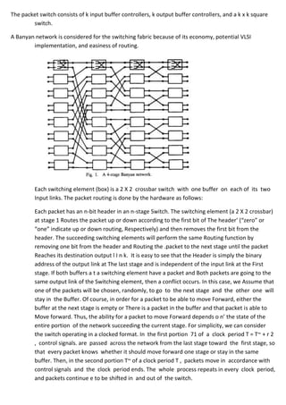
  • 1. The packet switch consists of k input buffer controllers, k output buffer controllers, and a k x k square switch. A Banyan network is considered for the switching fabric because of its economy, potential VLSI implementation, and easiness of routing. Each switching element (box) is a 2 X 2 crossbar switch with one buffer on each of its two Input links. The packet routing is done by the hardware as follows: Each packet has an n-bit header in an n-stage Switch. The switching element (a 2 X 2 crossbar) at stage 1 Routes the packet up or down according to the first bit of The header’ (“zero” or “one” indicate up or down routing, Respectively) and then removes the first bit from the header. The succeeding switching elements will perform the same Routing function by removing one bit from the header and Routing the .packet to the next stage until the packet Reaches its destination output l I n k. It is easy to see that the Header is simply the binary address of the output link at The last stage and is independent of the input link at the First stage. If both buffers a t a switching element have a packet and Both packets are going to the same output link of the Switching element, then a conflict occurs. In this case, we Assume that one of the packets will be chosen, randomly, to go to the next stage and the other one will stay in the Buffer. Of course, in order for a packet to be able to move Forward, either the buffer at the next stage is empty or There is a packet in the buffer and that packet is able to Move forward. Thus, the ability for a packet to move Forward depends o n’ the state of the entire portion of the network succeeding the current stage. For simplicity, we can consider the switch operating in a clocked format. In the first portion 71 of a clock period T = T~ + r 2 , control signals. are passed across the network from the last stage toward the first stage, so that every packet knows whether it should move forward one stage or stay in the same buffer. Then, in the second portion T~ of a clock period T , packets move in accordance with control signals and the clock period ends. The whole process repeats in every clock period, and packets continue e to be shifted in and out of the switch.