
Empfohlen
Weitere ähnliche Inhalte
Was ist angesagt?
Was ist angesagt? (20)
Andere mochten auch
Andere mochten auch (12)
Ähnlich wie Presentation on Vector Groups by Armstrong
Ähnlich wie Presentation on Vector Groups by Armstrong (20)
Presentation on Vector Groups by Armstrong
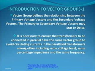
- 1. Vector Group defines the relationship between the Primary Voltage Vectors and the Secondary Voltage Vectors. The Primary or Secondary Voltage Vectors may Star or Delta. It is necessary to ensure that transformers to be connected in parallel have the same vector group to avoid circulating currents in the paralleled transformers among other including same voltage level, same percentage impedance and the same frequency. 5/3/2016 Presentation By; Armstrong Okai Ababio Electrical Engineer/ Electricity Company of Ghana
- 2. The concept of vector groups was adopted for transformers in the Generation, Transmission and Distribution Networks in a manner so as to avoid the transfer of Zero Sequence Current from each of the networks into the other. Delta Blocks the flow of Zero Sequence Current. The vector groups was also chosen in manner so as to enable the Earthing or grounding of the various networks to facilitate the control of earth fault current by the use of Neutral Ground Resistor(NGR). Where the Network is solidly earthed, the earthing system is designed based on the exact short circuit level of the Network, be it Generation, Transmission and Distribution. Resonant Grounding (Peterson Coil) is also used in countries like Germany, where the Reactance of the Peterson coil is tuned to match the Fictitious Capacitance of the network. This way the earth fault current is reduced to approximately Zero at the instant of fault (Inductive Current minus (-) Capacitive Current). By this means countries with these scheme do not normally trip on earth fault. 5/3/2016 Presentation By; Armstrong Okai Ababio Electrical Engineer/ Electricity Company of Ghana
- 3. The concept of vector groups was adopted for transformers in the Generation, Transmission and Distribution Networks in a manner so as to make the overall phase shift Zero (0) at the Distribution end close to the Customer. The following slides analysis the various vector group of the Generation, Transmission and Distribution Network of the Ghana Power System. 5/3/2016 Presentation By; Armstrong Okai Ababio Electrical Engineer/ Electricity Company of Ghana
- 4. Generation (Ynd1) Transmission (Ynd11) Shifts Star ahead Delta Nullifies the Phase shift by 30° by 30° by shifting Delta at 30 ° ahead Star Distribution (MV) (Dyn1) Distribution (LV) (Dyn11) Shifts Delta ahead Star Nullifies the Phase shift by 30° by 30° by shifting Star at 30 ° ahead Delta •RESULTANT PHASE SHIFT = ZERO (0) 5/3/2016 Presentation By; Armstrong Okai Ababio Electrical Engineer/ Electricity Company of Ghana
- 5. It can be seen clearly that the Resultant Phase Shift in the overall Vector Group of the Ghana Power System from Generation through to the Distribution (LV) Network is Zero (0). This way Customer end power is not affected by the overall vector group of the power system. The following slides show the various vector groups available for Star-Delta, Star-Star, Delta-Star and Delta-Delta Transformers. 5/3/2016 Presentation By; Armstrong Okai Ababio Electrical Engineer/ Electricity Company of Ghana
- 6. Delta – Star 5/3/2016 Presentation By; Armstrong Okai Ababio Electrical Engineer/ Electricity Company of Ghana C B A Primary Delta Equi. Secondary Star Options of Naming Transformer Secondary a b c b a c c b a A AA a a a 11 3 7
- 7. Delta – Star 5/3/2016 Presentation By; Armstrong Okai Ababio Electrical Engineer/ Electricity Company of Ghana C B A Primary Delta Equi. Secondary Star Options of Naming Transformer Secondary a b c b a c c b a A AA a a a 5 9 1
- 8. As clearly shown above, there are six vector group options available for Delta – Star Transformer Configuration. These are; Dy1 Dy3 Dy5 Dyn1 Dyn3 Dyn5 Or Dy7 Dy9 Dy11 Dyn7 Dyn9 Dyn11 5/3/2016 Presentation By; Armstrong Okai Ababio Electrical Engineer/ Electricity Company of Ghana
- 9. Star – Delta 5/3/2016 Presentation By; Armstrong Okai Ababio Electrical Engineer/ Electricity Company of Ghana C B A Primary Star Equi. Secondary Delta Options of Naming Transformer Secondary a b c b a c c b a A AA a a a 1 9 5
- 10. Star – Delta 5/3/2016 Presentation By; Armstrong Okai Ababio Electrical Engineer/ Electricity Company of Ghana C B A Primary Star Equi. Secondary Delta Options of Naming Transformer Secondary a b c b a c c b a A AA a a a 11 3 7
- 11. As clearly shown above, there are six vector group options available for Star – Delta Transformer Configuration. These are; Yd1 Yd3 Yd5 Ynd1 Ynd3 Ynd5 Or Yd7 Yd9 Yd11 Ynd7 Ynd9 Ynd11 5/3/2016 Presentation By; Armstrong Okai Ababio Electrical Engineer/ Electricity Company of Ghana Yd1 or Ynd1 is the same as Dy11 or Dyn11 as in both cases Star (Y) leads Delta (D) by 30°. Yd11 or Ynd11 is the same as Dy1 or Dyn1 as in both cases Delta (D) leads Star (Y) by 30°. Note: By Inspection
- 12. Delta – Delta 5/3/2016 Presentation By; Armstrong Okai Ababio Electrical Engineer/ Electricity Company of Ghana C B A Primary Delta Equi. Secondary Delta Options of Naming Transformer Secondary a b c b a c c b a A AA a a a 0 8 4
- 13. Delta – Delta 5/3/2016 Presentation By; Armstrong Okai Ababio Electrical Engineer/ Electricity Company of Ghana C B A Primary Delta Equi. Secondary Delta Options of Naming Transformer Secondary a b c b a c c b a A AA a a a 6 2 10
- 14. As clearly shown above, there are six vector group options available for Delta – Delta Transformer Configuration. These are; Dd0 Dd2 Dd4 Dd6 Dd8 Dd10 5/3/2016 Presentation By; Armstrong Okai Ababio Electrical Engineer/ Electricity Company of Ghana
- 15. Star – Star 5/3/2016 Presentation By; Armstrong Okai Ababio Electrical Engineer/ Electricity Company of Ghana C B A Primary Star Equi. Secondary Star Options of Naming Transformer Secondary a b c b a c c b a A AA a a a 0 8 4
- 16. Star – Star 5/3/2016 Presentation By; Armstrong Okai Ababio Electrical Engineer/ Electricity Company of Ghana C B A Primary Star Equi. Secondary Star Options of Naming Transformer Secondary a b c b a c c b a A AA a a a 6 2 10
- 17. As clearly shown above, there are six vector group options available for Star – Star Transformer Configuration. These are; Yy0 Yy2 Yy4 Yyn0 Yyn2 Yyn4 Or Yy6 Yy8 Yy10 Yyn6 Yyn8 Yyn10 5/3/2016 Presentation By; Armstrong Okai Ababio Electrical Engineer/ Electricity Company of Ghana
- 18. As clearly shown in the previous slides, there are Twenty-Four (24) vector groups for Star Delta Transformers. Below is the reiteration of these vector groups; Dy1 Dy3 Dy5 Or Dyn1 Dyn3 Dyn5 Dy7 Dy9 Dy11 Dyn7 Dyn9 Dyn11 Dd0 Dd2 Dd4 Dd6 Dd8 Dd10 Yd1 Yd3 Yd5 Or Ynd1 Ynd3 Ynd5 Yd7 Yd9 Yd11 Ynd7 Ynd9 Ynd11 Yy0 Yy2 Yy4 Or Ynyn0 Ynyn2 Ynyn4 Yy6 Yy8 Yy10 Ynyn6 Ynyn8 Ynyn10 5/3/2016 Presentation By; Armstrong Okai Ababio Electrical Engineer/ Electricity Company of Ghana
- 19. Dyn1 5/3/2016 Presentation By; Armstrong Okai Ababio Electrical Engineer/ Electricity Company of Ghana A C B c b a 30° 30° 30° The Primary Voltage Vectors (Delta) leads the Secondary Voltage Vectors (Star) by 30°. This is also known as lag in Aspen DistriView
- 20. Dyn11 5/3/2016 Presentation By; Armstrong Okai Ababio Electrical Engineer/ Electricity Company of Ghana A C B c b a 30° 30° 30° The Primary Voltage Vectors (Delta) lags the Secondary Voltage Vectors (Star) by 30°. This is also known as lead in Aspen DistriView
- 21. Thank You Very Much For Your Kind Attention 5/3/2016 Presentation By; Armstrong Okai Ababio Electrical Engineer/ Electricity Company of Ghana