SlideShare a Scribd company logo
1 of 2
Download to read offline
Easy-Laser®

Shaft documentation sheet
Always read the safety instructions in the main manual before using the measurement system.

Preparations                                                                               File information
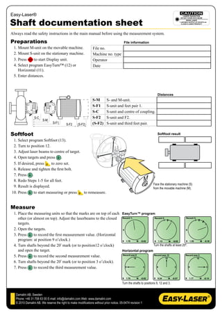
 1. Mount M-unit on the movable machine.                         File no.
 2. Mount S-unit on the stationary machine.                      Machine no. type
 3. Press     to start Display unit.                             Operator
 4. Select program EasyTurn™ (12) or                             Date
    Horizontal (11).
 5. Enter distances.


                                                                                                                       Distances
                                                                 S-M        S- and M-unit.
                                                                 S-F1       S-unit and feet pair 1.
                                                                 S-C        S-unit and centre of coupling.
                  S-C                                            S-F2       S-unit and F2.
                        S-M
                                 S-F1       S-F2     (S-F2)      (S-F2)     S-unit and third feet pair.

Softfoot                                                                                                               Softfoot result
 1. Select program Softfoot (13).
 2. Turn to position 12.
 3. Adjust laser beams to centre of target.
 4. Open targets and press .
 5. If desired, press    to zero set.
 6. Release and tighten the first bolt.
 7. Press .
 8. Redo Steps 1-5 for all feet.
                                                                                                                   Face the stationary machine (S)
 9. Result is displayed.                                                                                           from the movable machine (M).
10. Press     to start measuring or press   to remeasure.


Measure
 1. Place the measuring units so that the marks are on top of each EasyTurn™ program
    other (or almost on top). Adjust the laserbeams to the closed
    targets.
 2. Open the targets.
 3. Press     to record the first measurement value. (Horizontal
    program: at position 9 o’clock.)
 4. Turn shafts beyond the 20º mark (or to position12 o’clock)                        Turn the shafts at least 20º.
    and open the target.                                           Horizontal program
 5. Press     to record the second measurement value.
 6. Turn shafts beyond the 20º mark (or to position 3 o’clock).
 7. Press     to record the third measurement value.


                                                                                         Turn the shafts to positions 9, 12 and 3.


   Damalini AB, Sweden
   Phone: +46 31 708 63 00 E-mail: info@damalini.com Web: www.damalini.com
   © 2010 Damalini AB. We reserve the right to make modifications without prior notice. 05-0474 revision 1
Easy-Laser®

 Results                                                                                        Offset Tolerance
 The result is displayed. Horizontal and vertical positions for the                                            Excellent           Acceptable
 movable machine are shown both digitally and graphically. The                                   rpm           mils     mm         mils   mm
 values now updates continuously (live), indicated by filled foot
                                                                                                 0000-1000     3.0      0.07       5.0    0.13
 symbols.
 The result from a measurement of a horizontal machine displays                                  1000-2000     2.0      0.05       4.0    0.10
 the position of the movable machine, and how to shim and adjust to                              2000-3000     1.5      0.03       3.0    0.07
 align the machine.                                                                              3000-4000     1.0      0.02       2.0    0.04
                                                                                                 4000-5000     0.5      0.01       1.5    0.03
                                                                     Vertical
                                                                     Offset value                5000-6000     <0.5     <0.01      <1.5   <0.03
                                                                     Angular value
                                                                     Adjustment value
                                                                                                Angular error Tolerance
                                                                                                               Excellent           Acceptable
                                                                     Horizontal
                                                                     Offset value
                                                                                                 rpm           mils/” mm/100       mils/” mm/100
                                                                     Angular value               0000-1000     0.6      0.06       1.0    0.10
                                                                     Adjustment value            1000-2000     0.5      0.05       0.8    0.08
                                                                                                 2000-3000     0.4      0.04       0.7    0.07
                                  Indicator for measurement direction.
                                  EasyTurn™ program: shows the real position of the units.       3000-4000     0.3      0.03       0.6    0.06
                                  Horizontal program: the indicator shows how the units have     4000-5000     0.2      0.02       0.5    0.05
                                  to be positioned for live values ± 1.5º.
                                                                                                 5000-6000     0.1      0.01       0.4    0.04

                 Vertical results                                Horizontal results
                                                                                                                      Tolerance check.
Target                                Offset value                                             Offset value
values                                                                                                                Horizontal program:
                                      Angular value                                            Angular value
                                                                                                                      changes between Horizontal
                                                                                                                      and Vertical live values.
         Adjustment value   Adjustment value                Adjustment value     Adjustment value
                                                                                                                      Thermal growth compensation.

                                                                                                                      Remeasure.

  1


  2


  3


  4


      www.damalini.com

More Related Content

What's hot

Pumps_alignment_1684283213.pdf
Pumps_alignment_1684283213.pdfPumps_alignment_1684283213.pdf
Pumps_alignment_1684283213.pdfNagsSuresh
 
Single Rotor, Two Rotor and Three Rotor Torsional Vibration System
Single Rotor, Two Rotor and Three Rotor Torsional Vibration SystemSingle Rotor, Two Rotor and Three Rotor Torsional Vibration System
Single Rotor, Two Rotor and Three Rotor Torsional Vibration SystemDevan P.D
 
Alignment sample
Alignment sampleAlignment sample
Alignment sampleHasan Monem
 
Types of gears
Types of gearsTypes of gears
Types of gearsGoa App
 
Vibration monitoring and its features for corelation
Vibration monitoring and its features for corelationVibration monitoring and its features for corelation
Vibration monitoring and its features for corelationBoben Anto Chemmannoor
 
Shaft Alignment Trainer [SAT] presentation
Shaft Alignment Trainer [SAT] presentationShaft Alignment Trainer [SAT] presentation
Shaft Alignment Trainer [SAT] presentationSpectra Quest Inc
 
Bearings and lubrications
Bearings and lubricationsBearings and lubrications
Bearings and lubricationsMuhammad Nadeem
 
Rotating Equipment Vibration Analysis.pdf
Rotating Equipment Vibration Analysis.pdfRotating Equipment Vibration Analysis.pdf
Rotating Equipment Vibration Analysis.pdfAdil229465
 
Orbit anlysis vibration
Orbit anlysis vibrationOrbit anlysis vibration
Orbit anlysis vibrationAchdzul
 
Bearing Description about basic, types, failure causes
Bearing Description about basic, types, failure causesBearing Description about basic, types, failure causes
Bearing Description about basic, types, failure causesPankaj
 

What's hot (20)

Pumps_alignment_1684283213.pdf
Pumps_alignment_1684283213.pdfPumps_alignment_1684283213.pdf
Pumps_alignment_1684283213.pdf
 
Single Rotor, Two Rotor and Three Rotor Torsional Vibration System
Single Rotor, Two Rotor and Three Rotor Torsional Vibration SystemSingle Rotor, Two Rotor and Three Rotor Torsional Vibration System
Single Rotor, Two Rotor and Three Rotor Torsional Vibration System
 
Shaft Lateral Analysis Overview
Shaft Lateral Analysis OverviewShaft Lateral Analysis Overview
Shaft Lateral Analysis Overview
 
Bump test (Resonance Test)
Bump test (Resonance Test)Bump test (Resonance Test)
Bump test (Resonance Test)
 
Alignment sample
Alignment sampleAlignment sample
Alignment sample
 
Types of gears
Types of gearsTypes of gears
Types of gears
 
Vibration monitoring and its features for corelation
Vibration monitoring and its features for corelationVibration monitoring and its features for corelation
Vibration monitoring and its features for corelation
 
Shaft Alignment
Shaft AlignmentShaft Alignment
Shaft Alignment
 
Soft foot
Soft footSoft foot
Soft foot
 
Shaft Alignment Trainer [SAT] presentation
Shaft Alignment Trainer [SAT] presentationShaft Alignment Trainer [SAT] presentation
Shaft Alignment Trainer [SAT] presentation
 
Coupling Alignment
Coupling Alignment Coupling Alignment
Coupling Alignment
 
Machine drawing
Machine drawingMachine drawing
Machine drawing
 
Vibration
VibrationVibration
Vibration
 
Alignment presentation
Alignment presentationAlignment presentation
Alignment presentation
 
Bearings and lubrications
Bearings and lubricationsBearings and lubrications
Bearings and lubrications
 
Rotating Equipment Vibration Analysis.pdf
Rotating Equipment Vibration Analysis.pdfRotating Equipment Vibration Analysis.pdf
Rotating Equipment Vibration Analysis.pdf
 
Misalignment
Misalignment Misalignment
Misalignment
 
Differential Gear train
Differential Gear trainDifferential Gear train
Differential Gear train
 
Orbit anlysis vibration
Orbit anlysis vibrationOrbit anlysis vibration
Orbit anlysis vibration
 
Bearing Description about basic, types, failure causes
Bearing Description about basic, types, failure causesBearing Description about basic, types, failure causes
Bearing Description about basic, types, failure causes
 

Viewers also liked

Viewers also liked (7)

Transcat and Fluke Present: Precision Shaft Alignment Made Easy
Transcat and Fluke Present: Precision Shaft Alignment Made EasyTranscat and Fluke Present: Precision Shaft Alignment Made Easy
Transcat and Fluke Present: Precision Shaft Alignment Made Easy
 
Inch To Millimeter Conversion Table
Inch To Millimeter Conversion TableInch To Millimeter Conversion Table
Inch To Millimeter Conversion Table
 
Millimeter To Inch Conversion Table
Millimeter To Inch Conversion TableMillimeter To Inch Conversion Table
Millimeter To Inch Conversion Table
 
Decimal Equivalents Of Number Size Drills
Decimal Equivalents Of Number Size DrillsDecimal Equivalents Of Number Size Drills
Decimal Equivalents Of Number Size Drills
 
10 Inch Diameter
10 Inch Diameter10 Inch Diameter
10 Inch Diameter
 
5.alignment
5.alignment5.alignment
5.alignment
 
Balancing of rotating masses
Balancing of rotating massesBalancing of rotating masses
Balancing of rotating masses
 

More from AmericanMillwright (20)

Triangle Chart
Triangle ChartTriangle Chart
Triangle Chart
 
Steam Turbinesforcombinedcycle
Steam TurbinesforcombinedcycleSteam Turbinesforcombinedcycle
Steam Turbinesforcombinedcycle
 
How To Use A Transit Final2
How To Use A Transit Final2How To Use A Transit Final2
How To Use A Transit Final2
 
Ge Steam Turbinesfor Industrial
Ge Steam Turbinesfor IndustrialGe Steam Turbinesfor Industrial
Ge Steam Turbinesfor Industrial
 
Ge Steam Turbine Products
Ge Steam Turbine ProductsGe Steam Turbine Products
Ge Steam Turbine Products
 
Layout Basics I Ne
Layout Basics I NeLayout Basics I Ne
Layout Basics I Ne
 
Metric &amp; Inch Equivalent
Metric &amp; Inch EquivalentMetric &amp; Inch Equivalent
Metric &amp; Inch Equivalent
 
Millimeter Tap Drill Sizes
Millimeter Tap Drill SizesMillimeter Tap Drill Sizes
Millimeter Tap Drill Sizes
 
Siemens1000 Mw
Siemens1000 MwSiemens1000 Mw
Siemens1000 Mw
 
Siemens Fuel Gasifier
Siemens Fuel GasifierSiemens Fuel Gasifier
Siemens Fuel Gasifier
 
Siemens Gas Turbine4000 F
Siemens Gas Turbine4000 FSiemens Gas Turbine4000 F
Siemens Gas Turbine4000 F
 
Soft Foot
Soft FootSoft Foot
Soft Foot
 
Ge Combined Cycle
Ge Combined CycleGe Combined Cycle
Ge Combined Cycle
 
Carbon Capture
Carbon CaptureCarbon Capture
Carbon Capture
 
Compressor Valves
Compressor ValvesCompressor Valves
Compressor Valves
 
Coal Reburning
Coal ReburningCoal Reburning
Coal Reburning
 
Millwright Entire Packet
Millwright  Entire PacketMillwright  Entire Packet
Millwright Entire Packet
 
Nccer Rigger
Nccer RiggerNccer Rigger
Nccer Rigger
 
Nccer Maintenance
Nccer MaintenanceNccer Maintenance
Nccer Maintenance
 
Nccer Millwright
Nccer MillwrightNccer Millwright
Nccer Millwright
 

Easy Laser Shaft Alignment Worksheet

  • 1. Easy-Laser® Shaft documentation sheet Always read the safety instructions in the main manual before using the measurement system. Preparations File information 1. Mount M-unit on the movable machine. File no. 2. Mount S-unit on the stationary machine. Machine no. type 3. Press to start Display unit. Operator 4. Select program EasyTurn™ (12) or Date Horizontal (11). 5. Enter distances. Distances S-M S- and M-unit. S-F1 S-unit and feet pair 1. S-C S-unit and centre of coupling. S-C S-F2 S-unit and F2. S-M S-F1 S-F2 (S-F2) (S-F2) S-unit and third feet pair. Softfoot Softfoot result 1. Select program Softfoot (13). 2. Turn to position 12. 3. Adjust laser beams to centre of target. 4. Open targets and press . 5. If desired, press to zero set. 6. Release and tighten the first bolt. 7. Press . 8. Redo Steps 1-5 for all feet. Face the stationary machine (S) 9. Result is displayed. from the movable machine (M). 10. Press to start measuring or press to remeasure. Measure 1. Place the measuring units so that the marks are on top of each EasyTurn™ program other (or almost on top). Adjust the laserbeams to the closed targets. 2. Open the targets. 3. Press to record the first measurement value. (Horizontal program: at position 9 o’clock.) 4. Turn shafts beyond the 20º mark (or to position12 o’clock) Turn the shafts at least 20º. and open the target. Horizontal program 5. Press to record the second measurement value. 6. Turn shafts beyond the 20º mark (or to position 3 o’clock). 7. Press to record the third measurement value. Turn the shafts to positions 9, 12 and 3. Damalini AB, Sweden Phone: +46 31 708 63 00 E-mail: info@damalini.com Web: www.damalini.com © 2010 Damalini AB. We reserve the right to make modifications without prior notice. 05-0474 revision 1
  • 2. Easy-Laser® Results Offset Tolerance The result is displayed. Horizontal and vertical positions for the Excellent Acceptable movable machine are shown both digitally and graphically. The rpm mils mm mils mm values now updates continuously (live), indicated by filled foot 0000-1000 3.0 0.07 5.0 0.13 symbols. The result from a measurement of a horizontal machine displays 1000-2000 2.0 0.05 4.0 0.10 the position of the movable machine, and how to shim and adjust to 2000-3000 1.5 0.03 3.0 0.07 align the machine. 3000-4000 1.0 0.02 2.0 0.04 4000-5000 0.5 0.01 1.5 0.03 Vertical Offset value 5000-6000 <0.5 <0.01 <1.5 <0.03 Angular value Adjustment value Angular error Tolerance Excellent Acceptable Horizontal Offset value rpm mils/” mm/100 mils/” mm/100 Angular value 0000-1000 0.6 0.06 1.0 0.10 Adjustment value 1000-2000 0.5 0.05 0.8 0.08 2000-3000 0.4 0.04 0.7 0.07 Indicator for measurement direction. EasyTurn™ program: shows the real position of the units. 3000-4000 0.3 0.03 0.6 0.06 Horizontal program: the indicator shows how the units have 4000-5000 0.2 0.02 0.5 0.05 to be positioned for live values ± 1.5º. 5000-6000 0.1 0.01 0.4 0.04 Vertical results Horizontal results Tolerance check. Target Offset value Offset value values Horizontal program: Angular value Angular value changes between Horizontal and Vertical live values. Adjustment value Adjustment value Adjustment value Adjustment value Thermal growth compensation. Remeasure. 1 2 3 4 www.damalini.com