Airflow: The 4 Elements of Cleanroom Construction Part 2
•Als PPTX, PDF herunterladen•
5 gefällt mir•2,999 views

One way AMTS is “Constructing an Intelligent Tomorrow” is through the work of our Cleanroom Performance Solutions group. In this 4-part series, our very own Emil Bordelon, a NEBB Certified Professional, outlines the four main elements of a cleanroom that are considered during the design, certification and maintenance phases. http://amcleanroombuild.com/

Empfohlen
Empfohlen
Weitere ähnliche Inhalte
Andere mochten auch
Kürzlich hochgeladen
Kürzlich hochgeladen (20)
Airflow: The 4 Elements of Cleanroom Construction Part 2
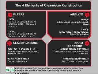
- 1. 1 AM Technical Solutions ConfidentialAM Technical Solutions Confidential © AM Technical Solutions, Inc. All rights reserved The 4 Elements of Cleanroom Construction FILTERS AIRFLOW CLASSIFICATIONS ROOM PRESSURE AMTS is a National Environmental Balancing Bureau (NEBB) Certified Firm Copyright AM Technical Solutions, Constructing an Intelligent Tomorrow www.amts.com HEPA Minimum Efficiency of 99.9997% ISO Class 5 (100) – ISO Class 8 (100,000) ULPA Minimum Efficiency of 99.9997% ISO Class 1 – ISO Class 4 (10) 1 2 43 Design Unidirectional, Non-Unidirectional, Mixed Testing Airflow Velocity, Airflow Volume, Airflow Visualization ISO 14644-1 Classes 1 – 9 Formerly referred to as the Federal Standard 209E Facility Certification Semi-annual or annual Differential Room Pressure Create airflow from a clean area to a less clean area Recommended Pressure .03 to .05 inches of water gauge
- 2. 2 AM Technical Solutions ConfidentialAM Technical Solutions Confidential © AM Technical Solutions, Inc. All rights reserved The 4 Elements of Cleanroom Design, Certification and Maintenance Part 2
- 3. 3 AM Technical Solutions Confidential © AM Technical Solutions, Inc. All rights reserved In this 4-part series, AM Technical Solution’s very own Emil Bordelon, a NEBB Certified Professional, outlines the four main elements of a cleanroom that are considered during the design, certification and maintenance phases. The 4 elements are: HEPA/ ULPA filters Airflow Cleanroom Classification Room Pressure
- 4. 4 AM Technical Solutions Confidential © AM Technical Solutions, Inc. All rights reserved Element 2: Airflow Airflow Design There are 3 different types of airflow in a cleanroom: 1. Unidirectional Airflow: • Unidirectional airflow is defined in ISO 14644-4 as “Controlled airflow through the entire cross-section of a clean zone with a steady velocity and approximately parallel streamlines”. • It is also specified as ≤ 14º form perpendicular when performing airflow parallelism. • In IEST RP-CC006.2 it is recommended that a unidirectional airflow cleanroom have at less 80% filter coverage. • ISO Class 1 through 5 are recommended to be unidirectional airflow designs (see ISO 14644-4 table B.2 below). Below is an example of a unidirectional airflow cleanroom:
- 5. 5 AM Technical Solutions Confidential © AM Technical Solutions, Inc. All rights reserved Airflow Design 2. Non-Unidirectional Airflow: • Non-unidirectional airflow is defined in ISO 14644-4 as “Air distribution where the supply air entering the clean zone mixes with the internal air by means of induction”. • ISO Class 6 through 9 are recommended to be non- unidirectional airflow designs (see ISO 14644-4 table B.2 below). Below is an example of a non-unidirectional airflow cleanroom:
- 6. 6 AM Technical Solutions Confidential © AM Technical Solutions, Inc. All rights reserved 3. Mixed Airflow: • Mixed airflow is defined in ISO 14644-4 as “A combination of both Unidirectional and Non-Unidirectional airflows”. Below is an example of a mixed airflow cleanroom: Airflow Design
- 7. 7 AM Technical Solutions Confidential © AM Technical Solutions, Inc. All rights reserved
- 8. 8 AM Technical Solutions Confidential © AM Technical Solutions, Inc. All rights reserved Airflow Testing: There are two methods for measuring airflow depending on the type of airflow used. 1. Unidirectional Airflow: • The airflow velocity method is used in unidirectional airflow cleanroom. • A test instrument is used to measure the speed of the air as it exits the HEPA / ULPA filter. • There should be a uniformed airflow speed of ± 15 %. In some cases a tighter specification is called for. • The speed is measure in feet per minute or meters per second. • In ISO 14644-4 Table B.2 it gives a range of the room airflow velocity for each ISO Class 1 through 3. • This is the room airflow velocity not the HEPA / ULPA filter. • They can be different depending on filter coverage and ceiling height
- 9. 9 AM Technical Solutions Confidential © AM Technical Solutions, Inc. All rights reserved Airflow Testing 2. Non-Unidirectional and Mixed Airflow: • The airflow volume method is used in non-unidirectional and mixed airflow cleanrooms. • A capture hood is used to measure the volume of air exiting the HEPA / ULPA filter. • The test results are reported in cubic feet per minute or liters per second. • The total airflow for the room is divided by the room volume to calculate the room air change rate per hour. • In ISO 14644-4 Table B.2 it gives a range of air changes per hour for each ISO Class 6 through 9.
- 10. 10 AM Technical Solutions Confidential © AM Technical Solutions, Inc. All rights reserved Airflow Visualization: There are two methods for airflow visualization measurement: 1. Parallelism: • Airflow parallelism is used in unidirectional airflow cleanrooms to visualize airflow. • Using a plum bob and a non-shedding thread that has high surface area to weight ratio (flow viz) to measure the angle of deflection of the airstream from perpendicular. Below is example of a parallelism test stand:
- 11. 11 AM Technical Solutions Confidential © AM Technical Solutions, Inc. All rights reserved Airflow Visualization 2. Airflow Directional Test: • Airflow directional test is used in non-unidirectional airflow cleanrooms. • This test involves using visible vapor to visualize the direction of the airflow and the effects of process equipment to the airflow. • The pharmaceutical industry uses this method for both unidirectional and non-unidirectional airflow cleanrooms for this reason. Below is an example of an airflow directional test stand:
- 12. 12 AM Technical Solutions Confidential © AM Technical Solutions, Inc. All rights reserved Cleanroom Design: Utilizing ISO 14644-4 Table B.2 air change rates and room velocities the basic airflow design for a cleanroom can be made. Below are two examples of cleanrooms one unidirectional and the other non-unidirectional. 1. Non-Unidirectional Design: • This example is an ISO class 6 cleanroom 20’ by 20’ with 10’ ceilings. • The room volume is 4,000 cubic feet. • The recommended air change rate range by ISO 14644-4 for class 6 is 70 to 160 per hour. • Selecting the mid range of 115 air changes per hour the total volume per hour need is 460,000 cubic feet per hour (4,000 x 115). • Divide the total volume per hour by 60 will give us 7,667 cubic feet per minute. • Using the specified 720 cubic feet per minute per filter we divide 7,667 by 720 we get 10.6 round it up to 11 filters. • This would equate out to 1.98 changes per minute or 118 changes per hour. • This room would have a filter coverage of 22%.
- 13. 13 AM Technical Solutions Confidential © AM Technical Solutions, Inc. All rights reserved Cleanroom Design: Utilizing ISO 14644-4 Table B.2 air change rates and room velocities the basic airflow design for a cleanroom can be made. 2. Unidirectional Design: • This example is an ISO class 4 cleanroom 20’ by 20’ with 10’ ceilings. • The room volume is 4,000 cubic feet. • The recommended room velocity by ISO 14644-4 for class 4 is 0.3 is 0.5 meters per second (59 to 98 feet per minute). • Selecting the mid range of 75 feet per minute the total volume need is 30,000 cubic feet per minute (4,000 x 75). • Using the specified 720 cubic feet per minute per filter we divide 30,000 by 720 we get 41.6 round it up to 42 filters. • This would equate out to 75.6 feet per minute. • This room would have a filter coverage of 84%. • Utilizing ISO 14644-4 Table B.2 a very basic airflow design can be made but other factors will need to consider before a final cleanroom design is made. • Some of these factors are; exhaust air, make up air, manufacturing process, type of filters to be used, etc. but by understanding the principle of airflow design these choice should be easier.
- 14. 14 AM Technical Solutions Confidential © AM Technical Solutions, Inc. All rights reserved Putting this to use: • For over twenty years, our Cleanroom Performance Solutions team has provided cleanroom testing, certification, reporting, construction and consultation services across multiple markets, such as Semiconductor, Life Sciences, Technology and Research. • With over 30 years of experience, and the NEBB Certification, the AM Technical Solutions Engineers and Technicians can identify and analyze cleanroom performance problems; and suggest the most effective solutions or self-perform the corrections. • Our Engineers and Technicians are experienced in the most sensitive environments such as ISO 14644, Class 1 through Class 9, and have helped develop the industry’s standard protocols and testing specifications, as well as some of the key instrumentation, testing media, and standard documentation in use today. View previously posted The 4 Elements of Cleanroom Construction Part 1