

Empfohlen
Weitere ähnliche Inhalte
Was ist angesagt?
Was ist angesagt? (20)
Ähnlich wie Lecture dc machines
Ähnlich wie Lecture dc machines (20)
Mehr von sudeep kumar
Kürzlich hochgeladen
Kürzlich hochgeladen (20)
Lecture dc machines
- 1. DC Machines
- 2. DC Machines A DC Machine Armature along with the commutator
- 3. Significant Features of DC Machines • Conventional DC generators are being replaced by the solid state rectifiers where ac supply is available. • The same is not true for dc motors because of – Constant mechanical power output or constant torque – Rapid acceleration or deceleration – Responsiveness to feedback signals • 1W to 10,000 hp • Applications – in electric vehicles to extend their range and reduce vehicle weight, in steel and aluminum rolling mills, traction motors, electric trains, overhead cranes, control devices, etc.
- 4. Introduction Electromagnetic Energy Conversion: 1. When armature conductors move in a magnetic field produced by the current in stator field winding, voltage is induced in the armature conductors. 2. When current carrying armature conductors are placed in a magnetic field produced by the current in stator field winding, the armature conductors experience a mechanical force. These two effects occur simultaneously in a DC machine whenever energy conversion takes place from electrical to mechanical or vice versa.
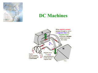
- 5. Electromagnetic Force, f f=Bli, where B, f and i are mutually perpendicular. Turn the current vector i towards the flux vector B. If a right hand screw is turned in the same way, the direction in which the screw will move represents the direction of the force f.
- 6. Motional Voltage, e e=Blv, where B, v and e are mutually perpendicular. The polarity of the induced voltage can be determined from the right hand screw rule. Turn the vector v towards the vector B. If a right hand screw is turned in the same way the motion of the screw will indicate the direction of positive polarity of the induced voltage e.
- 7. Constructional Features of DC Machines • Commutator along with the armature on the rotor • Salient-pole on the stator and, except for a few smaller machines, commutating poles between the main poles. • Field windings (as many as 4): – Two fields that act in a corrective capacity to combact the detrimental effects of armature reaction, called the commutating (compole or interpole) and compensating windings, which are connected in series with the armature. – Two normal exciting field windings, the shunt and series windings
- 8. Schematic Connection Diagram of a DC Machine
- 9. Equivalent Circuit of a DC Machine aaat fff RIEV RIV ±= = Ia_gen If Vf Vt Rf + - Ea + - Ia_mot Ra + Ia If Vt Rf Ea - IL Ra + + -
- 10. Generated emf and Electromagnetic Torque aaat fff RIEV RIV ±= = mdaa KE ωφ= adae IKT φ= meaaem TIEP ω== Voltage generated in the armature circuit due the flux of the stator field current Electromagnetic torque Ka: design constant Motor: Vt > Ea Generator: Vt > Ea
- 11. Comparison between the Shunt and Series Connected DC Machines
- 12. Armature Reaction If a load is connected to the terminals of the dc machine, a current will flow in its armature windings. This current flow will produce a magnetic field of its own, which will distort the original magnetic field from the machine’s field poles. This distortion of the magnetic flux in a machine as the load is increased is called the armature reaction.
- 13. Types of DC Machines Both the armature and field circuits carry direct current in the case of a DC machine. Types: Self-excited DC machine: when a machine supplies its own excitation of the field windings. In this machine, residual magnetism must be present in the ferromagnetic circuit of the machine in order to start the self-excitation process. Separately-excited DC machine: The field windings may be separately excited from an eternal DC source. Shunt Machine: armature and field circuits are connected in parallel. Shunt generator can be separately-excited or self-excited. Series Machine: armature and field circuits are connected in series.
- 14. Separately-Excited and Self-Excited DC Generators If IL If DC Supply Vt Rf + - Ea + - Ra + Ia Vt Rf Ea - IL Ra + Separately-Excited Self-Excited
- 15. Example 1 A 100-kW, 250-V DC shunt generator has an armature resistance of 0.05 Ω and field circuit resistance of 60 Ω. With the generator operating at rated voltage, determine the induced voltage at (a) full load, and (b) half-full load.
- 16. Solution to Example 1 (a) At full load, Vt=Ea-IaRa If=250/60=4.17 A IL_FL=100,000/250=400 A Ia=IL_FL+If=400+4.17=404.17 A Ea=Vt+IaRa=250+404.17*0.05=270.2 V (b) At half load, If=250/60=4.17 A IL_HL=50,000/250=200 A Ia=IL_HL+If=200+4.17=204.17 A Ea=Vt+IaRa=250+204.17*0.05=260.2 V
- 17. DC Generator Characteristics In general, three characteristics specify the steady-state performance of a DC generators: 1. Open-circuit characteristics: generated voltage versus field current at constant speed. 2. External characteristic: terminal voltage versus load current at constant speed. 3. Load characteristic: terminal voltage versus field current at constant armature current and speed.
- 18. DC Generator Characteristics Open-circuit and load characteristics The terminal voltage of a dc generator is given by ( )[ ] aa mf aaat RI dropreactionArmatureIf RIEV − −= −= ω,
- 19. DC Generator Characteristics It can be seen from the external characteristics that the terminal voltage falls slightly as the load current increases. Voltage regulation is defined as the percentage change in terminal voltage when full load is removed, so that from the external characteristics, External characteristics 100 V VE regulationVoltage t ta × − =
- 20. Self-Excited DC Shunt Generator Schematic diagram of connection Open-circuit characteristic Maximum permissible value of the field resistance if the terminal voltage has to build up.
- 21. Speed Control in DC Motors © N. Chowdhury of U of Saskatchewan
- 22. Speed Control in DC Motors Shunt motor: Electromagnetic torque is Te=Ka φd Ia, and the conductor emf is Ea=Vt - RaIa. For armature voltage control: Ra and If are constant For field control: Ra and Vt are constant For armature resistance control: Vt and If are constant ( )221 etm TKVK −=ω ( ) ( )32 e ff a ff t m T IK R IK V −=ω ( ) ( )12 da ae da t m a da e tmda K RT K V R K T VK φ − φ =ω φ −=ωφ ( ) ( )42 e da adja da t m T K RR K V φ + − φ =ω
- 23. Speed Control in Shunt DC Motors Armature Voltage Control: Ra and If are kept constant and the armature terminal voltage is varied to change the motor speed. For constant load torque, such as applied by an elevator or hoist crane load, the speed will change linearly with Vt. In an actual application, when the speed is changed by varying the terminal voltage, the armature current is kept constant. This method can also be applied to series motor. ( ) .constis; K K; K K TKVK d dada etm φ φ = φ = −=ω 221 21 11
- 24. Field Control: Ra and Vt are kept constant, field rheostat is varied to change the field current. For no-load condition, Te=0. So, no-load speed varies inversely with the field current. Speed control from zero to base speed is usually obtained by armature voltage control. Speed control beyond the base speed is obtained by decreasing the field current. If armature current is not to exceed its rated value (heating limit), speed control beyond the base speed is restricted to constant power, known as constant power application. Speed Control in Shunt DC Motors mm aa e meaaat .constIE T TIEconstIVP ω = ω = ω==== ( ) e ff a ff t m T IK R IK V 2 −=ω
- 25. Armature Resistance Control: Vt and If are kept constant at their rated value, armature resistance is varied. The value of Radj can be adjusted to obtain various speed such that the armature current Ia (hence torque, Te=KaφdIa) remains constant. Armature resistance control is simple to implement. However, this method is less efficient because of loss in Radj. This resistance should also been designed to carry armature current. It is therefore more expensive than the rheostat used in the field control method. Speed Control in Shunt DC Motors ( ) ee da adja da t m TKKT K RR K V 652 −= φ + − φ =ω
- 26. Armature Voltage Control: A variable dc voltage can be applied to a series motor to control its speed. A variable dc voltage can be obtained from a power electronic converter. Torque in a series motor can be expressed as Speed Control in Series DC Motors ( )[ ] sae t sa sa sae t m samsa tsa asaadae KKT V KK RR KKT V ,or RRKK VKK IKKIKT ≈ + −=ω ++ω = =φ= 2 2 2 ( ) ( ) ( ) ( ) samsa t a saamasa saamda saaat asd RRKK V I RRIIKK RRIK RRIEV IK ++ω = ++ω= ++ωφ= ++= =φ
- 27. Field Control: Control of field flux in a sries motor is achieved by using a diverter resistance. The developed torque can be expressed as. Speed Control in Series DC Motors ds d sa aa ds d saadae RR R andKKK,where IKI RR R KKIKT + =ρ= ρ= + =φ= 22 ( ) ( ) ( ) asm t a aasm aasmasa aasamda aaa ds ds at RRK V I,or IRRK IRRIKK RIRIK RII RR RR EV +ρ+ρω = +ρ+ρω= +ρ+ωρ= +ρ+ωφ= + + +=
- 28. Speed Control in Series DC Motors 2 +ρ+ρω ρ= asm t e RRK V KT
- 29. Armature Resistance Control: Torque in this case can be expressed as Rae is an external resistance connected in series with the armature. For a given supply voltage and a constant developed torque, the term (Ra+Rae+Rs+Kωm) should remain constant. Therefore, an increase in Rae must be accompanied by a corresponding decrease in ωm. Speed Control in Series DC Motors ( ) K RRR KT V ,or V T K KRRR,or T KV KRRR sadja e t m t e msadja e t msadja ++ −=ω =ω+++ =ω+++ 2 2 ( )2 2 msadja t e KRRR KV T ω+++ =
- 30. Power Division in DC Machines Input from prime-mover Elec-magnetic Power =EaIa Arm. terminal power = Vta Ia Output power = Vt IL No-load rotational loss (friction +windage+core)+stray load loss Arm. copper loss Ia 2 Ra+brush contact loss Series field loss IL 2 Rs +shunt field loss If 2 Rf Input power from mains =Vt IL Elec-magnetic Power =EaIa Arm. terminal power = Vta Ia Output available at the shaft No-load rotational loss (friction +windage+core)+stray load loss Arm. copper loss Ia 2 Ra+brush contact loss Series field loss IL 2 Rs +shunt field loss If 2 Rf DC Motor DC Generator
- 31. Efficiency InputPower Losses InputPower LossesInputPower InputPower OutputPower −= − = =η 1 The losses are made up of rotational losses (3-15%), armature circuit copper losses (3-6%), and shunt field copper loss (1-5%). The voltage drop between the brush and commutator is 2V and the brush contact loss is therefore calculated as 2Ia.
- 33. Problem 9-1 to 9-7 (Page 621)
- 34. Solution to Problem 9-1 (Page 621)
- 35. Solution to Problem 9-2 (Page 621)
- 36. Solution to Problem 9-5 (Page 621)
- 37. Problem 9-13 (Page 623)
- 38. Solution to Problem 9-13 (Page 623)
- 39. Solution to Problem 9-13 (Page 623)
- 40. The End