SlideShare ist ein Scribd-Unternehmen logo
1 von 322
4. Disconnect the washer nozzle hose and remove the cowl grille assembly.
5. Remove the wiper linkage clip from the motor output arm and pull the linkage from the
output arm.
6. Remove the pivot body to cowl screws and remove the linkage and pivot shaft assembly
(three screws on each side). The left and right pivots and linkage are independent and
can be serviced separately.
To install:
7. Attach the linkage and pivot shaft assembly to cowl with attaching screws.
8. Replace the linkage to the output arm and attach the linkage clip.
9. Connect the washer nozzle hose and cowl grills assembly.
10. Attach cowl grille attaching screws.
11. Replace both wiper arm assemblies.
12. Connect the negative battery cable.
Windshield Washer Fluid Reservoir
REMOVAL & INSTALLATION
1. Disconnect the wiring at the pump motor. Use a small prytool to unlock the connector
tabs.
2. Remove the washer hose.
3. Remove the reservoir attaching screws or nuts and lift the assembly from the truck.
Depending on the year, model and optional equipment, the reservoir could be on the
fender apron, radiator support, or air cleaner bracket.
NOTE: The cover is not removable from the reservoir.
Windshield Washer Motor
REMOVAL & INSTALLATION
Fig. 1: Washer motor replacement
1. Remove the reservoir.
2. Using a small prytool, pry out the motor retaining ring.
http://fordrazborka.zu8.ru/
3. Using pliers, grip one edge of the electrical connector ring and pull the motor, seal and
impeller from the reservoir.
NOTE: If the seal and impeller come apart from the motor, it can all be re-
assembled.
To install:
4. Take the time to clean out the reservoir before installing the motor.
5. Coat the seal with a dry lubricant, such as powdered graphite or spray Teflon® . This will
aid assembly.
6. Align the small projection on the motor end cap with the slot in the reservoir and install
the motor so that the seal seats against the bottom of the motor cavity.
7. Press the retaining ring into position. A 1 in., 12-point socket or length of 1 in. tubing, will
do nicely as an installation tool.
8. Install the reservoir and connect the wiring.
NOTE: It's not a good idea to run a new motor without filling the reservoir first.
Dry-running will damage a new motor.
INSTRUMENTS AND SWITCHES
Precautions
Electronic modules, such as instrument clusters, powertrain controls and sound systems are
sensitive to static electricity and can be damaged by static discharges which are below the
levels that you can hear "snap'' or detect on your skin. A detectable snap or shock of static
electricity is in the 3,000 volt range. Some of these modules can be damaged by a charge of as
little as 100 volts.
The following are some basic safeguards to avoid static electrical damage:
• Leave the replacement module in its original packing until you are ready to install it.
• Avoid touching the module connector pins
• Avoid placing the module on a non-conductive surface
• Use a commercially available static protection kit. These kits contain such things as
grounding cords and conductive mats.
Instrument Cluster
REMOVAL & INSTALLATION
Fig. 1: Cluster opening finish panels
http://fordrazborka.zu8.ru/
1. Disconnect the negative battery cable.
2. Remove the wiper-washer knob. Use a hook tool to release each knob lock tab.
3. Remove the knob from the headlamp switch. Remove the fog lamp switch knob, if so
equipped.
4. Remove the steering column shroud. Care must be taken not to damage the
transmission control selector indicator (PRNDL) cable on vehicles equipped with an
automatic transmission.
5. On vehicles equipped with an automatic transmission, remove the loop on the indicator
cable assembly from the retainer pin. Remove the bracket screw from the cable bracket
and slide the bracket out of the slot in the tube.
6. Remove the cluster trim cover. Remove the 4 cluster attaching screws, disconnect the
speedometer cable wire connector from the printed circuit, 4x4 indicator light and
remove the cluster.
7. Position the cluster at the opening and connect the multiple connector, the speedometer
cable and 4x4 indicator light. Install the 4 cluster retaining screws.
8. If so equipped, place the loop on the transmission indicator cable assembly over the
retainer on the column.
9. Position the tab on the steering column bracket into the slot on the column. Align and
attach the screw.
10. Place the transmission selector lever on the steering column into the DRIVE position.
11. Adjust the slotted bracket so the pin is within the letter band.
12. Install the trim cover.
13. Install the headlamp switch knob. If so equipped, install the fog lamp switch.
14. Install the wiper washer control knobs.
15. Connect the battery cable, and check the operation of all gauges, lights and signals.
Tachometer
REMOVAL & INSTALLATION
1. Disconnect the negative battery cable.
2. Remove the instrument cluster.
3. Remove the cluster mask and lens.
4. Remove the tachometer by prying the dial away from the cluster back plate. The
tachometer is retained by clips.
5. Installation is the reverse of removal. Make sure the clips are properly seated.
http://fordrazborka.zu8.ru/
Speedometer Cable Core
REMOVAL & INSTALLATION
Fig. 1: Speedometer driven gear-to-transmission
installation — all models
Fig. 2: Speedometer cable quick-disconnect
NOTE: 1988–96 models equipped with the 4.9L MFI, 5.0L MFI and 5.8L MFI engines have a
speed sensor attached to the transmission. This device sends information on vehicle
speed to the Engine Management System and Cruise Control System. For replacement of
this unit, see the Cruise Control procedures in this section.
1. Reach up behind the cluster and disconnect the cable by depressing the quick
disconnect tab and pulling the cable away.
2. Remove the cable from the casing. If the cable is broken, raise the vehicle on a hoist
and disconnect the cable from the transmission.
3. Remove the cable from the casing.
4. To remove the casing from the vehicle pull it through the floor pan.
http://fordrazborka.zu8.ru/
To install:
5. To replace the cable, slide the new cable into the casing and connect it at the
transmission.
6. Route the cable through the floor pan and position the grommet in its groove in the floor.
7. Push the cable onto the speedometer head.
Speedometer Head
REMOVAL & INSTALLATION
1. Remove the instrument cluster.
2. Disconnect the cable from the head.
3. Remove the lens and any surrounding trim.
4. Remove the 2 attaching screws.
5. Installation is the reverse of removal. Place a glob of silicone grease on the end of the
cable core prior to connection.
Fuel Gauge
REMOVAL & INSTALLATION
1. Disconnect the negative battery cable.
2. Remove the instrument cluster.
3. Remove the cluster mask and lens.
4. Remove the 2 nuts attaching the gauge to the cluster back plate.
5. Installation is the reverse of removal.
Windshield Wiper Switch
REMOVAL & INSTALLATION
1. Disconnect the negative battery cable.
2. Remove the switch knob, bezel nut and bezel.
3. Pull the switch out from under the panel and unplug the wiring.
4. Installation is the reverse of removal.
Headlight Switch
REMOVAL & INSTALLATION
1. Disconnect the negative battery cable.
2. Depending on the year and model remove the wiper-washer and fog lamp switch knob if
they will interfere with the headlight switch knob removal. Check the switch body (behind
dash, see Step 3) for a release button. Press in on the button and remove the knob and
shaft assembly. If not equipped with a release button, a hook tool may be necessary for
knob removal.
3. Remove the steering column shrouds and cluster panel finish panel if they interfere with
the required clearance for working behind the dash.
4. Unscrew the switch mounting nut from the front of the dash. Remove the switch from the
back of the dash and disconnect the wiring harness.
5. Install in reverse order.
LIGHTING
http://fordrazborka.zu8.ru/
Headlights
REMOVAL & INSTALLATION
Fig. 1: Twist it counterclockwise
Fig. 2: DO NOT touch the headlight bulb glass — if you do,
wipe it clean with an alcohol soaked paper towel
CAUTION
The headlamp bulb contains high pressure halogen gas. The bulb may shatter if scratched or
dropped! Hold the bulb by its plastic base only. If you touch the glass portion with your fingers,
or if any dirt or oily deposits are found on the glass, it must be wiped clean with an alcohol
soaked paper towel. Even the oil from your skin will cause the bulb to burn out prematurely due
to hot-spotting.
1. Make sure that the headlight switch is OFF.
2. Raise the hood and find the bulb base protruding from the back of the headlamp
assembly
3. Disconnect the wiring by grasping the connector and snapping it rearward firmly.
http://fordrazborka.zu8.ru/
4. Rotate the bulb retaining ring counterclockwise (rear view) about 1
⁄8 turn and slide it off
the bulb base. Don't lose it; it's re-usable.
5. Carefully pull the bulb straight out of the headlamp assembly. Don't rotate it during
removal.
WARNING
Don't remove the old bulb until you are ready to immediately replace it! Leaving the
headlamp assembly open, without a bulb, will allow foreign matter such as water, dirt,
leaves, oil, etc. to enter the housing. This type of contamination will cut down on the
amount and direction of light emitted, and eventually cause premature blow-out of the
bulb.
To install:
6. With the flat side of the bulb base facing upward, insert it into the headlamp assembly.
You may have to turn the bulb slightly to align the locating tabs. Once aligned, push the
bulb firmly into place until the bulb base contacts the mounting flange in the socket.
7. Place the retaining ring over the bulb base, against the mounting flange and rotate it
clockwise to lock it. It should lock against a definite stop when fully engaged.
8. Snap the electrical connector into place. A definite snap will be felt.
9. Turn the headlights on and check that everything works properly.
AIMING
Fig. 1: Headlamp adjustment points
The headlights must be properly aimed to provide the best, safest road illumination. The lights
should be checked for proper aim and adjusted as necessary. Certain state and local authorities
have requirements for headlight aiming; these should be checked before adjustment is made.
Each headlight is adjusted by means of 2 screws located at the 10 o'clock and 3 o'clock
positions on the headlight underneath the trim ring. Always bring each beam into final position
by turning the adjusting screws clockwise so that the headlight will be held against the tension
springs when the operation is completed.
Headlight adjustment may be temporarily made using a wall, as described below, or on the rear
of another vehicle. When adjusted, the lights should not glare in oncoming car or truck
windshields, nor should they illuminate the passenger's compartment of vehicles driving in front
http://fordrazborka.zu8.ru/
of you. These adjustments are rough and should always be fine-tuned by a repair shop which is
equipped with headlight aiming tools. Improper adjustments may be both dangerous and illegal.
Before making any headlight adjustments, perform the following preparatory steps:
1. Make sure all tires are properly inflated.
2. Take into consideration any faulty wheel alignment or improper rear axle tracking.
3. Make sure there is no load in the truck other than the driver.
4. The truck's fuel tank should be about half full.
5. Make sure all lenses are clean.
To adjust:
6. Park the truck on a level surface, with the fuel tank no more than 1
⁄2 full and with the
vehicle empty of all extra cargo (unless normally carried). The vehicle should be facing a
wall which is no less than 6 feet (1.8m) high and 12 feet (3.7m) wide. The front of the
vehicle should be about 25 feet (7.6m) from the wall.
7. If this is be performed outdoors, it is advisable to wait until dusk in order to properly see
the headlight beams on the wall. If done in a garage, darken the area around the wall as
much as possible by closing shades or hanging cloth over the windows.
8. Turn the headlights ON and mark the wall at the center of each light's low beam, then
switch on the "brights'' and mark the center of each light's high beam. A short length of
masking tape which is visible from the front of the truck may be used. Although marking
all 4 positions is advisable, marking 1 position from each light should be sufficient.
9. If neither beam on one side of the vehicle is working, park another like-sized truck in the
exact spot where the truck was and mark the beams using the same side light on that
truck. Then switch the trucks so the truck being worked on is back in the original spot.
The truck must be parked no closer to or farther away from the wall than the second
vehicle.
10. Perform the necessary repairs, but make sure the truck is not moved or is returned to
the exact spot from which the lights were marked. Turn the headlights ON and adjust the
beams to match the marks on the wall.
11. Have the headlight adjustment checked as soon as possible by a reputable repair shop.
Signal and Marker Lights
REMOVAL & INSTALLATION
Front Turn Signal and Parking Lights
1. Remove the headlamp assembly attaching screws.
2. Pull the headlamp assembly out and disconnect the parking lamp socket from the
headlamp body.
3. Replace the bulb.
4. Installation is the reverse of removal.
Rear Turn Signal, Brake and Parking Lights
STYLE SIDE PICK-UPS AND BRONCO
Fig. 1: Remove the screws from the rear of the rear light lens
http://fordrazborka.zu8.ru/
Fig. 2: Lower the tailgate, then remove the retaining screw
from the rear lens
Fig. 3: Twist the bulb socket counterclockwise, then pull it
from the light assembly
http://fordrazborka.zu8.ru/
Fig. 4: Pull the affected bulb from the socket and replace it
with the correct type bulb
1. Remove the screws that attach the combination light lens assembly and remove the
lens.
2. Turn the affected bulb socket counterclockwise to remove the bulb; clockwise to install a
new bulb.
FLARE SIDE PICK-UPS
Fig. 5: Roof marker lamps for all models
http://fordrazborka.zu8.ru/
The bulbs can be replaced by removing the lens (4 screws). To replace the lamp assembly,
remove the 3 nuts from the mounting studs, disconnect the wiring inside the frame rail, unhook
the wiring from the retaining clip, pull out the wires and remove the lamp assembly.
High-mount Brake Light
Fig. 6: Remove the retaining screws from the hi-mount brake
light
Fig. 7: Turn the light bulb socket to disengage it from the light
assembly
http://fordrazborka.zu8.ru/
Fig. 8: Pull out the bulb from the socket — always replace it
with the specified bulb
1. Remove the 2 screws that retain the hi-mount light.
2. Pull the rear hi-mount light away from the top.
3. To remove the bulb, disconnect the socket from the light assembly, then pull out the
bulb.
4. To remove the light assembly, disconnect the wiring from the light, then remove the light.
5. Reverse the removal procedure to install.
Dome/ Map Light
BRONCO MODELS
1. Carefully pry the dome lamp lens, at the corners, from the housing.
2. Remove the 2 screws attaching the map lamp lens housing to the lamp base and
remove the bulbs. The lamp base is retained to the roof by 4 screws.
3. Installation is the reverse of removal.
http://fordrazborka.zu8.ru/
F-150, F-250, F-350 and F-SUPER DUTY MODELS
1. To replace the bulb, snap the lens out of the lamp body and remove the bulb.
2. To remove the lamp body, remove the 4 retaining screws.
3. Installation is the reverse of removal.
Cargo Lamp
F-150/250/350 AND SUPER-DUTY MODELS
Remove the 2 lamp retaining screws and remove the lamp. Remove the bulb from the lamp.
Installation is the reverse of removal.
BRONCO MODELS
Carefully unsnap the lamp from the side of the truck, disconnect the wiring and remove the bulb.
Installation is the reverse of removal.
Fig. 9: Remove the lens to access the dome light mounting
screws — F-150 shown, others similar
Fig. 10: Simply pull the bulb from its connections as
demonstrated
http://fordrazborka.zu8.ru/
TRAILER WIRING
Wiring the vehicle for towing is fairly easy. There are a number of good wiring kits available and
these should be used, rather than trying to design your own.
All trailers will need brake lights and turn signals as well as tail lights and side marker lights.
Most areas require extra marker lights for overly wide trailers. Also, most areas have recently
required back-up lights for trailers, and most trailer manufacturers have been building trailers
with back-up lights for several years.
Additionally, some Class I, most Class II and just about all Class III trailers will have electric
brakes. Add to this number an accessories wire, to operate trailer internal equipment or to
charge the trailer's battery, and you can have as many as seven wires in the harness.
Determine the equipment on your trailer and buy the wiring kit necessary. The kit will contain all
the wires needed, plus a plug adapter set which includes the female plug, mounted on the
bumper or hitch, and the male plug, wired into, or plugged into the trailer harness.
When installing the kit, follow the manufacturer's instructions. The color coding of the wires is
usually standard throughout the industry. One point to note: some domestic vehicles, and most
imported vehicles, have separate turn signals. On most domestic vehicles, the brake lights and
rear turn signals operate with the same bulb. For those vehicles with separate turn signals, you
can purchase an isolation unit so that the brake lights won't blink whenever the turn signals are
operated, or, you can go to your local electronics supply house and buy 4 diodes to wire in
series with the brake and turn signal bulbs. Diodes will isolate the brake and turn signals. The
choice is yours. The isolation units are simple and quick to install, but far more expensive than
the diodes. The diodes, however, require more work to install properly, since they require the
cutting of each bulb's wire and soldering in place of the diode.
One, final point, the best kits are those with a spring loaded cover on the vehicle mounted
socket. This cover prevents dirt and moisture from corroding the terminals. Never let the vehicle
socket hang loosely; always mount it securely to the bumper or hitch.
CIRCUIT PROTECTION
http://fordrazborka.zu8.ru/
Fuses
Fig. 1: Remove the cover from the fuse panel
Fig. 2: Use only the fuses specified for the circuit
Fig. 3: Firewall-mounted fuse box, turn signal and hazard
flashers
http://fordrazborka.zu8.ru/
Fig. 4: Instrument panel-mounted fuse box
On earlier models, the fuse panel is located on the firewall above the driver's left foot.
On later models, the fuse panel is located on the underside of the instrument panel, covered
with an access door.
Circuit Breakers
Two circuits are protected by circuit breakers located in the fuse panel: the power windows (20
amp) or power windows and Shift-On-The-Fly (30 amp) and the power door locks (30 amp). The
breakers are self-resetting.
Turn Signal and Hazard Flasher Locations
Both the turn signal flasher and the hazard warning flasher are mounted on the fuse panel. The
turn signal flasher is mounted on the front of the fuse panel, and the hazard warning flasher is
mounted on the rear of the fuse panel.
http://fordrazborka.zu8.ru/
Fuse Link
The fuse link is a short length of special, Hypalon (high temperature) insulated wire, integral with
the engine compartment wiring harness and should not be confused with standard wire. It is
several wire gauges smaller than the circuit which it protects. Under no circumstances should a
fuse link replacement repair be made using a length of standard wire cut from bulk stock or from
another wiring harness.
To repair any blown fuse link use the following procedure:
1. Determine which circuit is damaged, its location and the cause of the open fuse link. If
the damaged fuse link is one of three fed by a common No. 10 or 12 gauge feed wire,
determine the specific affected circuit.
2. Disconnect the negative battery cable.
3. Cut the damaged fuse link from the wiring harness and discard it. If the fuse link is one
of 3 circuits fed by a single feed wire, cut it out of the harness at each splice end and
discard it.
4. Identify and procure the proper fuse link and butt connectors for attaching the fuse link to
the harness.
5. To repair any fuse link in a 3-link group with one feed:
A. After cutting the open link out of the harness, cut each of the remaining
undamaged fuse links close to the feed wire weld.
B. Strip approximately 1
⁄2 in. (13mm) of insulation from the detached ends of the 2
good fuse links. Then insert 2 wire ends into one end of a butt connector and
carefully push one stripped end of the replacement fuse link into the same end of
the butt connector and crimp all three firmly together.
NOTE: Care must be taken when fitting the 3 fuse links into the butt
connector as the internal diameter is a snug it for 3 wires. Make sure to use
a proper crimping tool. Pliers, side cutters, etc. will not apply the proper
crimp to retain the wires and withstand a pull test.
C. After crimping the butt connector to the 3 fuse links, cut the weld portion from the
feed wire and strip approximately 1
⁄2 in. (13mm) of insulation from the cut end.
Insert the stripped end into the open end of the butt connector and crimp very
firmly.
D. To attach the remaining end of the replacement fuse link, strip approximately 1
⁄2
in. (13mm) of insulation from the wire end of the circuit from which the blown fuse
link was removed, and firmly crimp a butt connector or equivalent to the stripped
wire. Then, insert the end of the replacement link into the other end of the butt
connector and crimp firmly.
E. Using rosin core solder with a consistency of 60 percent tin and 40 percent lead,
solder the connectors and the wires at the repairs and insulate with electrical
tape.
6. To replace any fuse link on a single circuit in a harness, cut out the damaged portion,
strip approximately 1
⁄2 in. (13mm) of insulation from the 2 wire ends and attach the
appropriate replacement fuse link to the stripped wire ends with 2 proper size butt
connectors. Solder the connectors and wires and insulate the tape.
7. To repair any fuse link which has an eyelet terminal on one end such as the charging
circuit, cut off the open fuse link behind the weld, strip approximately 1
⁄2 in. (13mm) of
insulation from the cut end and attach the appropriate new eyelet fuse link to the cut
stripped wire with an appropriate size butt connector. Solder the connectors and wires at
the repair and insulate with tape.
8. Connect the negative battery cable to the battery and test the system for proper
operation.
http://fordrazborka.zu8.ru/
NOTE: Do not mistake a resistor wire for a fuse link. The resistor wire is generally
longer and has print stating, "Resistor: don't cut or splice."
WIRING DIAGRAMS
Fig. 1: Sample diagram — how to read and interpret wiring
Fig. 2: Common wiring diagram symbols
Fig. 3: Engine wiring — 1987–89 F-Series and Bronco 5.0L
(VIN N), 1988–89 F-Series and Bronco 5.8L (VIN H) and
1988–89 F-Series Pick-up 7.5L (VIN G) engines
Fig. 4: Engine wiring — 1987 F-Series Pick-up 7.5L (VIN G),
1987 F-Series and Bronco 5.8L (VIN H) engines
Fig. 5: Engine wiring — 1987–89 F-Series Pick-up 7.3L (VIN
M) diesel engine
Fig. 6: Engine wiring — 1987–88 F-Series Pick-up 4.9L (VIN
Y) engine
Fig. 7: Engine wiring — 1989 F-Series Pick-up 4.9L (VIN Y)
engine
Fig. 8: Engine wiring — 1990 F-Series Pick-up 7.5L (VIN G)
engine
Fig. 9: Engine wiring — 1990 F-Series Pick-up 4.9L (VIN Y)
engine
Fig. 10: Engine wiring — 1991 F-Series Pick-up 7.5L (VIN G)
engine
Fig. 11: Engine wiring — 1991 F-Series Pick-up 4.9L (VIN Y)
engine
Fig. 12: Engine wiring — 1990 F-Series and Bronco 5.0L
(VIN N) and 5.8L (VIN H)
Fig. 13: Engine wiring — 1991 F-Series and Bronco 5.0L
(VIN N) and 5.8L (VIN H)
Fig. 14: Engine wiring — 1990–93 F-Series Pick-up 7.3L (VIN
M) diesel engine
Fig. 15: Engine wiring — 1994–95 F-Series and Bronco 5.0L
Auto Transmission (VIN N) engine
Fig. 16: Engine wiring — 1994–95 F-Series and Bronco 5.0L
Manual Transmission (VIN N) engine
Fig. 17: Engine wiring — 1994 F-Series Pick-up 7.3L (VIN M)
diesel engine
Fig. 18: Engine wiring — 1992–94 F-Series 4.9L (VIN Y) and
1995 4.9L Federal (VIN Y) engines
http://fordrazborka.zu8.ru/
Fig. 19: Engine wiring — 1992–93 F-Series and Bronco 5.0L
(VIN N), 1992–94 F-Series and Bronco 5.8L (VIN H) and
1995 F-Series and Bronco 5.8L (VIN H) engine
Fig. 20: Engine wiring — 1995 F-Series 4.9L California (VIN
Y) engine
Fig. 21: Engine wiring — 1995 F-Series and Bronco 5.8L
California (VIN H) engine
Fig. 22: Engine wiring — 1992–95 F-Series 7.5L (VIN G),
1996 F-Series 7.5L Federal (VIN G) and 1996 F-Series Pick-
up 5.8L (VIN H over 8500 GVW) engines
Fig. 23: Engine wiring — 1994–96 F-Series Pick-up 7.3L (VIN
F) turbo diesel engines
Fig. 24: Engine wiring — 1996 F-Series and Bronco 5.0L
(VIN N), 5.8L (VIN H under 8500 GVW), 7.5L California (VIN
G) engines
Fig. 25: Engine wiring — 1996 F-Series 4.9L (VIN Y) engine
Fig. 26: Chassis wiring — 1987–89 F-Series and Bronco
Fig. 27: Chassis wiring — 1987–91 F-Series and Bronco
Fig. 28: Chassis wiring — 1990–91 F-Series and Bronco
Fig. 29: Chassis wiring — 1992 F-Series and Bronco
Fig. 30: Chassis wiring — 1992–96 F-Series and Bronco
Fig. 31: Chassis wiring — 1993–96 F-Series and Bronco
Fig. 32: TROUBLESHOOTING BASIC TURN SIGNAL AND
FLASHER PROBLEMS
DRIVE TRAIN
MANUAL TRANSMISSION
Adjustments
LINKAGE
3.03 Three Speed
Fig. 1: Aligning the shift rods at the steering column
http://fordrazborka.zu8.ru/
Fig. 2: Shift rod linkage adjustment position — E–150 to E–
350 shown
A column shift is used with this transmission.
1. Install a 3
⁄16 (4.76mm) diameter gauge pin, through the locating hole in the steering
column shift levers and the plastic spacer.
2. Locate the levers in the center of the steering column window.
3. Loosen nuts A and B and position the transmission shift levers in the Neutral detents.
4. Tighten nuts A and B to 12–18 ft. lbs. (17–24 Nm), using care to prevent motion
between the stud and rod.
5. Remove the gauge pin.
6. Check the linkage operation. Make sure there is no interference between the steering
column levers and window when shifting into gear.
NOTE: Always use new retaining rings and new insulators when making
transmission control adjustments. New retaining rings should also be used
whenever the existing retaining rings are removed. The rings as well as the plastic
http://fordrazborka.zu8.ru/
grommets where the shift rods are attached, should be replaced whenever
excessive wear or looseness is noted during normal vehicle inspections.
Ford TOD 4-Speed Overdrive
Fig. 3: Shifter mounting and linkage
A floor mounted shift is used with this transmission.
1. Attach the shift rods in the levers.
2. Rotate the output shaft to determine that the transmission is in Neutral.
3. Insert a alignment pin into the shift control assembly alignment hole.
4. Attach the slotted end of the shift rods over the flats of the studs in the shift control
assembly.
5. Install the locknuts and tighten the locknuts to 15–20 ft. lbs. (21–27 Nm). Remove the
alignment pin.
CLUTCH SWITCH
Fig. 1: Adjustable type clutch interlock switch
http://fordrazborka.zu8.ru/
Fig. 2: Non-adjustable type clutch interlock switch
The clutch interlock switch is used on all truck models, however this switch is adjustable in
some models up to 1991. On vehicles after 1991 the switch in non-adjustable. If the switch does
not function it must be replaced.
1. Disconnect the negative battery cable.
2. If the adjusting clip is out of position on the rod, remove both halves of the clip.
3. Position both halves of the clip closer to the switch and snap the clips together on the
rod.
4. Depress the clutch pedal to the floor to adjust the switch.
5. Connect the negative battery cable.
6. Check switch function by attempting to start the engine without depressing the clutch
pedal, the engine should not start. The engine should start when the clutch pedal is
depress.
CAUTION
Make sure the transmission is in
Neutral and the hand brake is applied when attempting to start the vehicle without the
clutch pedal depressed.
Shift Linkage
REMOVAL & INSTALLATION
3.03 Three Speed Transmission
NOTE: Most column mounted shift lever assemblies incorporate a plastic grommet in
each lever arm. A special tool T67P–7341 or equivalent is required to install the grommet
in the shaft lever and to install the shaft linkage rod into the grommet.
1. To remove the rod end connected to the shift column, place the lower jaw of the tool
between the shift lever and the shift rod. If working in limited space use tool T84P-341-A
or equivalent.
2. Position the stop pin against the end of the shift rod and force the rod out of the
grommet.
http://fordrazborka.zu8.ru/
3. The grommet is removed from the lever by cutting off the large shoulder of the grommet.
4. Remove the grommet from the lever by pushing it out of the lever.
5. Disconnect the rod at the transmission manual shift lever by removing the attaching nut
and remove the linkage.
To install:
6. Prior to installing a new grommet, adjust the stop pin if necessary to properly install the
grommet. Coat the outside of the grommet with a Multipurpose Long Life lubricant. Then
place the grommet on the stop pin and force it into the shift lever hole. Turn the grommet
several times to be sure it is properly seated.
7. Re-adjust the stop pin to a length which is sufficient to install the shift rod into the
grommet. If the pin height is not adjusted, the shaft rod may be pushed too far through
the grommet, causing damage to the grommet retaining lip.
8. With the pin height properly adjusted, position the shift rod on the tool and force the rod
into the grommet until the groove in the rod seats on the inner retaining lip of the
grommet.
9. Install the shift rods to the correct shift lever and install the retaining nuts. Do not tighten.
10. Adjust the shift linkage as described in this section.
4-Speed Overdrive Transmission
Fig. 1: Exploded view of the shifter assembly
1. Raise the vehicle and safely support it with jackstands.
NOTE: The shift linkage consist of 3 shift rods connected between the shifter and
transmission. If all shift rods are being removed, matchmark each rod to the lever
it is being removed from. This will insure proper installation location of each rod.
2. Disconnect the 3 shift rods at the transmission end by removing the retainer clip and
washer then pull each rod free from the shift lever. A bushing should be inside the eye of
the shift linkage. Replace this bushing if required.
3. Disconnect the shift linkage at the shifter end by removing the locknuts and remove the
shift linkage from the vehicle.
To install:
http://fordrazborka.zu8.ru/
4. Install the shift rods one at a time to the correct locations marked.
5. Replace the bushing at the end of the rod (transmission side) as required.
6. Connect the rod to the transmission shift lever and install the washer and retainer clip.
7. Connect the rod to the shifter and install the locknut, but do not tighten. Adjust the shift
linkage. See the above procedure.
8. Remove the jackstands and lower the vehicle.
Shift Handle
REMOVAL & INSTALLATION
Borg Warner T-18 and T-19; New Process 435 4-Speed Overdrive
NOTE: Remove the shift ball only if the shift ball, boot or lever is the be replaced. If either
the ball, boot or lever is not being replaced, remove the ball, boot and lever as an
assembly.
1. Disconnect the negative battery cable.
2. Remove the plastic insert from the shift ball. Warm the ball with a heat gun to 140–180°F
(60–82°C) knock the ball off the lever with a block of wood and a hammer taking care
not damage the finish on the shift lever.
3. Remove the rubber boot and floor pan cover.
4. Except 4 speed overdrive transmission, shift the unit into second gear, remove the
lockpin and remove the shift lever from the shifter housing.
5. Vehicles with 4 speed overdrive transmission, shift the unit into second gear. Depress
the retainer clip on the end of the shift lever and remove the shift lever from the housing.
To install:
6. Except 4 speed overdrive transmission, install the shift lever in the shifter housing,
making sure that the slot in the lever aligns with the tab in the housing. Install the
lockpin.
7. Vehicles with 4 speed overdrive transmission, install the shift lever in the shifter housing,
making sure that the retaining clip on the lever aligns with the slot in the housing and
snaps into place. Install the lockpin.
8. Install the rubber boot and floor pan cover.
9. Warm the ball with a heat gun to 140–180°F (60–82°C) and tap the ball on the lever with
a 7
⁄16 inch socket and mallet. Install the plastic shift pattern insert.
10. Vehicles with 4 speed overdrive transmission, the shifter is removed by depressing the
retainer clip on the end of the shift lever.
11. Connect the negative battery cable.
Ford TOD 4-Speed Overdrive
NOTE: Remove the shift ball only if the shift ball, boot or lever is to be replaced. If neither
the ball, boot nor lever is not being replaced, remove the ball, boot and lever as an
assembly.
1. Disconnect the negative battery cable.
2. Remove the plastic insert from the shift ball. Warm the ball with a heat gun to 140–180°F
(60–82°C) knock the ball off the lever with a block of wood and a hammer taking care
not damage the finish on the shift lever.
3. Remove the screws retaining the boot and pad to the floor plate.
4. Shift the transmission into Neutral.
5. Remove the boot from the cap. Place an oil filter wrench around the gearshift housing
cap and twist off the cap.
http://fordrazborka.zu8.ru/
WARNING
Do not twist the gearshift housing cap by hand. Due to the clearance between the floor
plate and cap, the hands may be cut.
6. Remove the shift lever from the transmission.
To install:
7. Install the shift lever in the gearshift housing, making sure that the slots in the lever
aligns with the pins in the housing.
8. Install the rubber boot and pad. Install the screws retaining the boot and pad to the floor
plate.
9. Warm the ball with a heat gun to 140–180°F (60–82°C) and tap the ball on the lever with
a 7
⁄16 inch socket and mallet. Install the plastic shift pattern insert.
10. Connect the negative battery cable.
ZF S5–42 and ZF S5–47
1. Disconnect the negative battery cable.
2. Remove the shifter boot and bezel assembly from the transmission opening cover.
3. Remove the 2 bolts retaining the upper shift lever to the lower shift lever and remove the
upper shift lever.
To install:
4. Install the upper shift lever to the lower lever and install the retaining bolts. Tighten 16–
24 ft. lbs. (22–33 Nm).
5. Install shifter boot and bezel assembly to the transmission opening cover.
6. Install the shift ball on the upper shifter if removed.
7. Connect the negative battery cable.
Mazda M50D 5-Speed
Fig. 1: Removing the shifter boot retaining screws
Fig. 2: Pull the boot up over the shift lever, exposing the
sound deadening material
http://fordrazborka.zu8.ru/
Fig. 3: Examine the condition of the boot and sound
deadening material
Fig. 4: If removing the shift lever from the stub shaft, install
and tighten the locknut from the opposite side
Fig. 5: The shift lever can be removed from the stub shaft by
removing the shift lever-to-stub shaft bolt
Fig. 6: To remove the shift lever and stub shaft together,
remove the shift dust cover retaining screws
http://fordrazborka.zu8.ru/
Fig. 7: Removing the shift lever assembly with the stub shaft
1. Disconnect the negative battery cable.
2. Shift the transmission into Neutral
3. Remove the carpet or floor mats.
4. Remove the shifter boot retainer screws and slide the boot up the shift lever shaft.
5. Remove the shift lever retaining bolt locknut.
6. Remove the shift lever retaining bolt by placing the locknut on the opposite end of the
bolt and tightening to loosen the bolt.
7. The shifter may be removed either by removing the bolt retaining the shifter to the shifter
stub and then pulling the shifter off or by removing the screws retaining the shifter to the
shift housing and remove the shifter and boot assembly.
To install:
8. If shifter was removed from the shifter stub shaft, install the retaining bolt in the shift
lever hole so that the flat aligns with the mating flat on the transmission stub shaft. Push
the bolt fully into position. Install the nut and tighten to 12–18 ft. lbs. (16–24 Nm).
9. If the shifter and stub shaft were removed together, position the shifter lever into the shift
housing aligning the end of the shifter with the slot in the transmission. Install the
retaining screws and tighten to 6–8 ft. lbs. (8–11 Nm).
10. Slide the gearshift boot and sound deadening material into position on the gearshift lever
and housing, then install the retaining screws.
11. Install the Isolator pan assembly. Install the floor pan cover and floor carpet it removed.
12. Connect the negative battery cable.
http://fordrazborka.zu8.ru/
Back-up Light Switch
REMOVAL & INSTALLATION
Fig. 1: Typical back-up lamp switch located — mounted on
the transmission
3.03 3-Speed
The back-up light switch is located on the transmission assembly.
1. Disconnect the negative battery cable.
2. Raise and support the vehicle safely with jackstands.
3. Disengage the harness from the back-up light switch.
4. Using a suitable wrench or ratchet/socket, remove the switch from the transmission.
To install:
5. Tread the back-up light switch into the transmission. Tighten the switch 8–12 ft. lbs. (11–
16 Nm).
6. Engage the harness to the switch.
7. Remove the jackstands and lower the vehicle
8. Connect the negative battery cable. Check switch operation.
4-Speed Overdrive Transmission
The Back-up light switch is mounted on to the floor shift assembly on the transmission extension
housing on F150–F250 or on a bracket attached to the transmission case for E150–E350
vehicles.
1. Disconnect the negative battery cable.
2. Place the transmission shift lever in any gear except Reverse.
3. Raise and support the vehicle safely with jackstands.
4. Disengage the electrical connector from the switch.
5. Using a suitable wrench or ratchet/socket, remove the switch from the shifter housing.
To install:
http://fordrazborka.zu8.ru/
6. Install the back-up light switch into the floor shift assembly or to the transmission case.
7. Engage the harness to the switch.
8. Remove the jackstands and lower the vehicle
9. Connect the negative battery cable. Check switch operation.
Borg Warner T-18 and T-19; New Process 435; TOD 4 Speed Overdrive
Fig. 2: Back-up light switch — located on the shifter housing
The back-up light switch is located at the rear of the gear shift housing cover.
1. Disconnect the negative battery cable.
2. Raise and support the vehicle safely with jackstands.
3. Disengage the harness from the back-up light switch.
4. Using a suitable wrench or ratchet/socket, remove the switch from the transmission.
To install:
5. Tread the back-up light switch into the transmission. Tighten the switch 15–25 ft. lbs.
(20–47 Nm) for T–18 and T–19 or 20–30 ft. lbs. (28–54 Nm) for NP 435 transmission.
6. Engage the harness to the switch.
7. Remove the jackstands and lower the vehicle
8. Connect the negative battery cable. Check switch operation.
Extension Housing Seal
REMOVAL & INSTALLATION
2WD Models
Fig. 1: Removing the extension housing seal
http://fordrazborka.zu8.ru/
Fig. 2: Always replace the old seal with a new one
Fig. 3: Using a special tool and mallet, install the new seal
The extension seal on 2WD drive vehicles is located at the rear of the transmission case.
1. Raise and support the vehicle safely.
2. Drain the transmission of lubricant.
3. Matchmark the driveshaft to the yoke for reassembly and remove the driveshaft.
4. Remove the old seal using a seal puller or appropriate prytool.
To install:
http://fordrazborka.zu8.ru/
5. Install a new seal, coated with sealing compound, using an appropriate seal installation
tool.
NOTE: Tool J-35582 or equivalent is recommended for AX4/5/15 transmissions.
Tool J-21426 or equivalent is recommended for Warner T4/5 transmissions.
6. Install the driveshaft, making certain to align the matchmark.
7. Fill the transmission to the level of the fill plug hole. Install the plug and lower the vehicle.
4WD Models
The extension seal on 4WD drive vehicles is located at the rear of the transfer case.
Transmission Assembly
REMOVAL & INSTALLATION
Fig. 1: Before removing the crossmember bolt, always have
the transmission supported
Fig. 2: With the transmission jack in place, remove the frame-
to-crossmember bolts
http://fordrazborka.zu8.ru/
Fig. 3: Removing the frame-to-crossmember bolts on the
opposite side
Fig. 4: Disengage any connectors at the transmission
http://fordrazborka.zu8.ru/
Fig. 5: With the transmission jack in place, remove the
transmission mount bolts
Fig. 6: Remove the bell housing bolts
http://fordrazborka.zu8.ru/
Fig. 7: Carefully pull the transmission away from the clutch
assembly until the input shaft is completely clear
CAUTION
The clutch driven disc may contain asbestos, which has been determined to be a cancer
causing agent. Never clean clutch surfaces with compressed air! Avoid inhaling any dust from
any clutch surface! When cleaning clutch surfaces, use a commercially available brake cleaning
fluid.
3.03 3-Speed
1. Disconnect the negative battery cable.
2. Raise the vehicle and safely support it with jackstands.
3. Support the engine with a jack and wood under the oil pan.
4. Drain the transmission.
5. Disconnect the gear shift linkage at the transmission.
6. Disconnect the speedometer cable. Disengage the harness from the back-up light
switch.
7. Remove the driveshaft.
http://fordrazborka.zu8.ru/
8. Raise the transmission just enough to remove the rear support, insulator and retainer
assembly.
9. Position a transmission jack under the transmission and secure it to the jack.
10. Remove the transmission-to-flywheel housing attaching bolts.
11. Move the transmission to the rear until the input shaft clears the clutch housing.
12. Carefully lower the transmission from the vehicle.
To install:
NOTE: Prior to installing the transmission, apply a light film of a Multi-Purpose
Long-life lubricant to the release bearing inner hub surfaces, release lever
fulcrum, fork and transmission front bearing retainer. Be sure to exercise care to
avoid contaminating the clutch disc with grease.
13. Secure the transmission on the transmission jack.
14. Raise the transmission until the input shaft splines are in-line with the clutch disc splines.
The clutch release bearing and hub must be properly positioned in the release lever fork.
15. Install a guide stud in each lower flywheel housing-to-transmission case mounting bolt
holes and align the splines on the input shaft with the spines on the clutch disc.
16. Slide the transmission forward on the guide studs until it contacts the clutch housing.
17. Install the 2 transmission-to-flywheel housing upper mounting bolts. Remove the 2 guide
studs and install the lower mounting bolts. Tighten the 4 mounting bolts to 42–50 ft. lbs.
(57–67 Nm).
18. Install the rear support, insulator and retainer assembly and tighten the attaching bolts
and nuts to 48–65 ft. lbs. (65–88 Nm).
19. Remove the transmission jack and engine jack.
20. Connect the speedometer cable and the driven gear.
21. Install the driveshaft.
22. Connect each shift rod to its respective lever on the transmission.
23. Install the lower extension housing-to-rear mount bolts and tighten to 60–80 ft. lbs. (82–
108 Nm). Install the rear mount-to-frame nuts to 50–70 ft. lbs. (68–94 Nm).
24. Adjust the shift linkage as required.
25. Connect the wiring to the back-up light switch.
Warner T-18, T-19A, T-19C 4-Speed
2-WHEEL DRIVE
1. Remove the rubber boot, floor mat, and the body floor pan cover.
2. Remove the gearshift lever, shift ball and boot as an assembly.
3. Raise the vehicle and support it with jackstands.
4. Drain the transmission.
5. Remove the driveshaft.
6. Disconnect the speedometer cable.
7. Remove the crossmember-to-transmission bolts.
8. Secure the transmission to a transmission jack.
9. Remove the crossmember.
10. Remove the 4 transmission-to-bell housing bolts, roll the transmission rearward and
remove it.
To install:
NOTE: You can make installation a lot easier if you fabricate 2 guide pins, made
by cutting the heads off of 2 long bolts. These guide pins are inserted into the
upper bolt holes in the back of the bell housing and serve to align the bolt holes.
http://fordrazborka.zu8.ru/
11. Raise the transmission and roll it forward using the guide pins to align the bolt holes.
Turn the output shaft by hand to align the input shaft splines with the clutch.
12. Install the 2 lower bolts and snug them down.
13. Remove the guide pins and install the 2 remaining bolts. Torque all 4 bolts to 50 ft. lbs.
(68 Nm).
14. Install the crossmember. Crossmember-to-frame bolt torque is 55 ft. lbs. (75 Nm).
15. Remove the transmission jack.
16. Install the Crossmember-to-transmission bolts. Tighten the bolts to 50 ft. lbs. (68 Nm).
17. Connect the speedometer cable.
18. Install the driveshaft.
19. Install the drain plug and fill the transmission. Drain plug torque is 50 ft. lbs. (68 Nm).
20. Lower the vehicle.
21. Install the gearshift lever, shift ball and boot as an assembly.
22. Install the body floor pan cover, floor mat, and the rubber boot.
4-WHEEL DRIVE
1. Remove the rubber boot, floor mat, and the body floor pan cover. Remove the gearshift
lever. Remove the weather pad.
2. Remove the transfer case shift lever, shift ball and boot as an assembly.
3. Disconnect the back-up light switch at the rear of the gearshift housing cover.
4. Raise the vehicle and support it with jackstands. Remove the drain and fill plugs and
drain the lubricant.
5. Position a transmission jack under the transfer case and disconnect the speedometer
cable.
6. Matchmark the flanges and disconnect the rear driveshaft from the transfer case. Wire it
up and out of the way.
7. Matchmark and disconnect the front driveshaft at the transfer case. Wire it up and out of
the way.
8. Remove the shift link from the transfer case.
9. Unbolt the transfer case from the transmission (6 bolts) and lower the transfer case from
the vehicle.
10. Position the transmission jack under the transmission.
11. Remove the 8 rear transmission support-to-transmission bolts.
12. Remove the rear transmission support.
13. Remove the 4 transmission-to-clutch housing attaching bolts.
14. Move the transmission to the rear until the input shaft clears the flywheel housing and
lower the transmission.
To install:
NOTE: You can make installation a lot easier if you fabricate 2 guide pins, made
by cutting the heads off of 2 long bolts. These guide pins are inserted into the
upper bolt holes in the back of the bell housing and serve to align the bolt holes.
15. Before installing the transmission, apply a light film of grease to the inner hub surface of
the clutch release bearing, the release lever fulcrum and the front bearing retainer of the
transmission. Do not apply excessive grease because it will fly off onto the clutch disc.
16. Install the transmission in the reverse order of removal. It may be necessary to turn the
output shaft with the transmission in gear to align the input shaft splines with the splines
in the clutch disc. Fill the transmission with SAE 80W/90 lubricant if it was drained. The
transfer case is filled with Dexron® II ATF. Observe the following torque specifications:
o Back-up light switch: 25 ft. lbs. (34 Nm)
o Transmission-to-clutch housing bolts: 65 ft. lbs. (88 Nm)
o Transfer case-to-transmission: 40 ft. lbs. (54 Nm)
o Drain plug: 50 ft. lbs. (68 Nm)
o Fill plug: 50 ft. lbs. (68 Nm)
http://fordrazborka.zu8.ru/
o Transmission to rear support: 80 ft. lbs. (108 Nm)
o Rear support-to-frame: 55 ft. lbs. (75 Nm)
New Process 435 4-Speed
2-WHEEL DRIVE
1. Remove the floor mat.
2. Remove the shift lever boot.
3. Remove the floor pan, transmission cover plate, and weather pad. It may be necessary
to remove the seat assembly.
4. Remove the shift lever and knob by first removing the inner cap using tool T73T–7220–
A, or equivalent. Then, remove the spring seat and spring. Remove the shift lever from
the housing.
5. Disconnect the back-up light switch located in the left side of the gearshift housing cover.
6. Raise the vehicle and place jackstands under the frame to support it. Place a
transmission jack under the transmission and disconnect the speedometer cable.
7. Matchmark and disconnect the driveshaft.
8. Remove the transmission rear support.
9. Remove the transmission-to-flywheel housing attaching bolts, slide the transmission
rearward until the input shaft clears the flywheel housing and lower it out from under the
truck.
10. Before installing the transmission, apply a light film of grease of the inner hub surface of
the clutch release bearing, release lever fulcrum and fork, and the front bearing retainer
of the transmission. Do not apply excessive grease because if will fly off and
contaminate the clutch disc.
11. Install the transmission in the reverse order of removal. It may be necessary to turn the
output shaft with the transmission in gear to align the input shaft splines with the splines
in the clutch disc. The front bearing retainer is installed through the clutch release
bearing. Observe the following torques:
o Transmission-to-clutch housing bolts: 65 ft. lbs. (88 Nm)
o Back-up light switch: 25 ft. lbs. (34 Nm)
o Drain and fill plugs: 30 ft. lbs. (41 Nm)
o Transmission-to-support: 80 ft. lbs. (108 Nm)
o Support-to-frame: 55 ft. lbs. (75 Nm)
4-WHEEL DRIVE
1. Remove the transmission lever rubber boot and floor mat.
2. Remove the transfer case shift lever, boot and ball as an assembly.
3. Remove the floor pan, transmission cover plate, and weather pad. It may be necessary
to remove the seat assembly.
4. Remove the shift lever and knob by first removing the inner cap using tool T73T–7220–
A, or equivalent. Then, remove the spring seat and spring. Remove the shift lever from
the housing.
5. Disconnect the back-up light switch located in the left side of the gearshift housing cover.
6. Raise the vehicle and place jackstands under the frame to support it. Place a
transmission jack under the transfer case and disconnect the speedometer cable.
7. Drain the transfer case.
8. Matchmark and disconnect the front driveshaft from the transfer case. Wire is up out of
the way.
9. Matchmark and disconnect the rear driveshaft from the transfer case. Wire it up out of
the way.
10. Disconnect the shift link from the transfer case.
11. Remove the 3 bolts securing the transfer case to the support bracket.
12. Remove the 6 bolts securing the transfer case to the transmission.
13. Lower the transfer case from the truck.
http://fordrazborka.zu8.ru/
14. Place the transmission jack under the transmission.
15. Remove the transmission rear support.
16. Remove the transmission-to-flywheel housing attaching bolts, slide the transmission
rearward until the input shaft clears the flywheel housing and lower it out from under the
truck.
To install:
17. Before installing the transmission, apply a light film of grease of the inner hub surface of
the clutch release bearing, release lever fulcrum and fork, and the front bearing retainer
of the transmission. Do not apply excessive grease because if will fly off and
contaminate the clutch disc.
18. Install the transmission in the reverse order of removal. It may be necessary to turn the
output shaft with the transmission in gear to align the input shaft splines with the splines
in the clutch disc. The front bearing retainer is installed through the clutch release
bearing. Observe the following torques:
o Back-up light switch: 25 ft. lbs. (34 Nm)
o Transmission-to-clutch housing bolts: 65 ft. lbs. (88 Nm)
o Drain and fill plugs: 30 ft. lbs. (41 Nm)
o Transmission-to-support: 80 ft. lbs. (108 Nm)
o Support-to-frame: 55 ft. lbs. (75 Nm)
o Transfer case-to-transmission: 40 ft. lbs. (54 Nm)
Ford TOD 4-Speed Overdrive
2-WHEEL DRIVE
1. Raise the truck and support it on jackstands. Drain the transmission.
2. Mark the driveshaft so that it can be installed in the same position.
3. Disconnect the driveshaft at the rear U-joint and slide it off the transmission output shaft.
4. Disconnect the speedometer cable, back-up light switch and high gear switch from the
transmission.
5. Remove the shift rods from the levers and the shift control from the extension housing.
6. Support the engine on a jack and remove the extension housing-to-crossmember bolts.
Raise the engine just high enough to take the weight off the rear crossmember. Remove
the crossmember.
7. Support the transmission on a jack and unbolt it from the clutch housing.
8. Move the transmission and jack rearward until clear. If necessary, lower the engine
enough for clearance.
To install:
9. Installation is the reverse of removal. It is a good idea to install and snug down the upper
transmission-to-engine bolts first, then the lower. For linkage adjustment, see the
beginning of this Section. check the fluid level. Observe the following torques:
o Back-up light switch: 25 ft. lbs. (34 Nm)
o Transmission-to-clutch housing bolts: 65 ft. lbs. (88 Nm)
o Drain and fill plugs: 30 ft. lbs. (41 Nm)
o Transmission-to-support: 80 ft. lbs. (108 Nm)
o Support-to-frame: 55 ft. lbs. (75 Nm)
4-WHEEL DRIVE
1. Raise the truck and support it on jackstands. Drain the transmission and transfer case.
2. Mark the driveshaft so that it can be installed in the same position.
3. Matchmark and disconnect the front and rear driveshafts at the transfer case.
http://fordrazborka.zu8.ru/
4. Disconnect the speedometer cable and 4WD drive indicator switch from the transfer
case; the back-up light switch and high gear switch from the transmission.
5. Remove the skid plate.
6. Disconnect the shift link from the transfer case.
7. Remove the shift lever from the transmission.
8. Support the transmission on a jack and remove the transmission housing rear support
bracket.
9. Raise the transmission just high enough to take the weight off the rear crossmember.
10. Remove the 2 nuts securing the upper gusset to the frame on both sides of the frame.
11. Remove the nut and bolt connecting the gusset to the support. Remove the gusset on
the left side.
12. Remove the transmission-to-support plate bolts.
13. Remove the support plate and right gusset.
14. Remove the crossmember.
15. Remove the transfer case heat shield. Be very careful if the catalytic converter is hot!
16. Support the transfer case on a jack and unbolt it from the transmission.
17. Move the transfer case and jack rearward until clear and lower it. Discard the adapter
gasket.
18. Support the transmission on a jack and unbolt it from the clutch housing.
19. Move the transmission and jack rearward until clear. If necessary, lower the engine for
clearance.
To install:
20. Installation is the reverse of removal. It is a good idea to install and snug down the upper
transmission-to-clutch housing bolts first, then the lower. For linkage adjustment, see the
beginning of this Section. Check the fluid level. Observe the following torques:
o Back-up light switch: 25 ft. lbs. (34 Nm)
o Transmission-to-clutch housing bolts: 65 ft. lbs. (88 Nm)
o Transfer case-to-transmission: 40 ft. lbs. (54 Nm)
o Rear driveshaft-to-yoke: 25 ft. lbs. (34)
o Front driveshaft-to-yoke: 15 ft. lbs. (20 Nm)
o Drain and fill plugs: 30 ft. lbs. (41 Nm)
o Transmission-to-support: 80 ft. lbs. (108 Nm)
o Support-to-frame: 55 ft. lbs. (75 Nm)
Mazda M5OD 5-Speed
1. Raise and support the truck on jackstands. Prop the clutch pedal in the full up position
with a block of wood.
2. Matchmark the driveshaft-to-flange relation.
3. Disconnect the driveshaft at the rear axle and slide it off of the transmission output shaft.
Lubricant will leak out of the transmission so be prepared to catch it, or plug the opening
with rags or a seal installation tool.
4. Disconnect the speedometer cable at the transmission.
5. Disconnect the shift rods from the shift levers.
6. Remove the shift control from the extension housing and transmission case.
7. On 4WD drive models, remove the transfer case.
8. Remove the extension housing-to-rear support bolts.
9. Take up the weight of the transmission with a transmission jack. Chain the transmission
to the jack.
10. Raise the transmission just enough to take the weight off of the No.3 crossmember.
11. Unbolt the crossmember from the frame rails and remove it.
12. Place a jackstand under the rear of the engine at the bell housing.
13. Lower the jack and allow the jackstand to take the weight of the engine. The engine
should be angled slightly downward to allow the transmission to roll backward.
http://fordrazborka.zu8.ru/
14. Remove the transmission-to bell housing bolts.
15. Roll the jack rearward until the input shaft clears the bell housing. Lower the jack and
remove the transmission.
WARNING
Do not depress the clutch pedal with the transmission removed.
To install:
16. Clean all machined mating surfaces thoroughly.
17. Install a guide pin in each lower bolt hole. Position the spacer plate on the guide pins.
18. Raise the transmission and start the input shaft through the clutch release bearing.
19. Align the input shaft splines with the clutch disc splines. Roll the transmission forward so
that the input shaft will enter the clutch disc. If the shaft binds in the release bearing,
work the release arm back and forth.
20. Once the transmission is all the way in, install the 2 upper retaining bolts and washers
and remove the lower guide pins. Install the lower bolts. Tighten the bolts to 50 ft. lbs.
(68 Nm).
21. Raise the transmission just enough to allow installation of the No. 3 crossmember.
22. Install the crossmember on the frame rails. Tighten the bolts to 80 ft. lbs. (108 Nm).
23. Lower the transmission onto the crossmember and install the nuts. Tighten the nuts to
70 ft. lbs. (95 Nm).
24. Remove the transmission jack.
25. The balance of installation is the reverse of removal.
ZF S5-42 and ZF S5-47 5-Speed
1. Place the transmission in Neutral.
2. Remove the carpet or floor mat.
3. Remove the ball from the shift lever.
4. Remove the boot and bezel assembly from the floor.
5. Remove the 2 bolts and disengage the upper shift lever from the lower shift lever.
6. Raise and support the tuck on jackstands.
7. Disconnect the speedometer cable.
8. Disconnect the back-up switch wire.
9. Place a drain pan under the case and drain the case through the drain plug.
10. Position a transmission jack under the case and safety-chain the case to the jack.
11. Remove the driveshaft.
12. Disconnect the clutch linkage.
13. On F-Super Duty models, remove the transmission-mounted parking brake. See Section
9.
14. On 4WD drive models, remove the transfer case.
15. Remove the transmission rear insulator and lower retainer.
16. Unbolt and remove the crossmember.
17. Remove the transmission-to-engine block bolts.
18. Roll the transmission rearward until the input shaft clears, lower the jack and remove the
transmission.
To install:
19. Install 2 guide studs into the lower bolt holes.
20. Raise the transmission until the input shaft splines are aligned with the clutch disc
splines. The clutch release bearing and hub must be properly positioned in the release
lever fork.
21. Position the transmission forward into the front case.
http://fordrazborka.zu8.ru/
22. Install and tighten the bolts to 50 ft. lbs. (68 Nm), then remove the guide studs and install
the 2 remaining bolts.
23. Install the crossmember, tighten the bolts to 55 ft. lbs. (68 Nm).
24. Install the transmission rear insulator and lower retainer. Tighten the bolts to 60 ft. lbs.
(81 Nm).
25. On 4WD drive models, install the transfer case.
26. The balance of installation is the reverse of removal.
CLUTCH
Clutch Disc and Pressure Plate
REMOVAL & INSTALLATION
Fig. 1: Remove the inspection plug to view the clutch
assembly components
Fig. 2: View of the clutch assembly with the transmission
removed
Fig. 3: Always use a clutch pilot tool during removal or
http://fordrazborka.zu8.ru/
installation of the clutch assembly
Fig. 4: Using a holding tool, hold the driveplate and remove
the clutch pressure plate-to-driveplate bolts
Fig. 5: When removing the pressure plate be careful not to
allow the fiction disc to drop
http://fordrazborka.zu8.ru/
Fig. 6: Examine the driveplate for cracks, heat spots and
scoring
Fig. 7: Using a holding tool, hold the drive plate and remove
the driveplate bolts
http://fordrazborka.zu8.ru/
Fig. 8: Exercise extreme care when removing the driveplate,
it is heavy
Fig. 9: View of the rear engine section with the driveplate
removed
http://fordrazborka.zu8.ru/
Fig. 10: Use a torque wrench to tighten the driveplate bolts
and a crisscross pattern
Fig. 11: With the clutch pilot tool in place, use a torque
wrench to tighten the pressure plate-to-driveplate bolts
http://fordrazborka.zu8.ru/
CAUTION
The clutch driven disc contains asbestos, which has been determined to be a cancer causing
agent. Never clean clutch surfaces with compressed air! Avoid inhaling any dust from any clutch
surface! When cleaning clutch surfaces, use a commercially available brake cleaning fluid.
1987 Models
1. Raise and support the truck end on jackstands.
2. Remove the clutch slave cylinder.
3. Remove the transmission.
4. If the clutch housing does not have a dust cover, remove the starter. Remove the
flywheel housing attaching bolts and remove the housing.
5. If the flywheel housing does have a dust cover, remove the cover and then remove the
release lever and bearing from the clutch housing. To remove the release lever:
A. Remove the dust boot.
B. Push the release lever forward to compress the slave cylinder.
C. On all engines except the diesel and the 7.5L gasoline engines, remove the
plastic clip that retains the slave cylinder to the bracket. Remove the slave
cylinder.
D. On the diesel and the 7.5L, the steel retaining clip is permanently attached to the
slave cylinder. Remove the slave cylinder by prying on the clip to free the tangs
while pulling the cylinder clear.
E. Remove the release lever by pulling it outward.
6. Mark the pressure plate and cover assembly and the flywheel so that they can be
reinstalled in the same relative position.
7. Loosen the pressure plate and cover attaching bolts evenly in a staggered sequence a
turn at time until the pressure plate springs are relieved of their tension. Remove the
attaching bolts.
8. Remove the pressure plate and cover assembly and the clutch disc from the flywheel.
To install:
9. Position the clutch disc on the flywheel so that an aligning tool or spare transmission
mainshaft can enter the clutch pilot bearing and align the disc.
10. When reinstalling the original pressure plate and cover assembly, align the assembly
and flywheel according to the marks made during removal. Position the pressure plate
http://fordrazborka.zu8.ru/
and cover assembly on the flywheel, align the pressure plate and disc, and install the
retaining bolts. Tighten the bolts in an alternating sequence a few turns at a time until the
proper torque is reached:
o 10 in. and 12 in. clutch: 15–20 ft. lbs. (20–27 Nm)
o 11 in. clutch: 20–29 ft. lbs. (27–39 Nm)
11. Remove the tool used to align the clutch disc.
12. With the clutch fully released, apply a light coat of grease on the sides of the driving
lugs.
13. Position the clutch release bearing and the bearing hub on the release lever. Install the
release lever on the fulcrum in the flywheel housing. Apply a light coating of grease to
the release lever fingers and the fulcrum. Fill the groove of the release bearing hub with
grease.
14. If the flywheel housing has been removed, position it against the rear engine cover plate
and install the attaching bolts and tighten them to 40–50 ft. lbs. (54–68 Nm).
15. Install the starter motor.
16. Install the transmission.
17. Install the salve cylinder and bleed the system.
1988–89 Models
1. Raise and support the truck end on jackstands.
2. On trucks with the externally mounted slave cylinder, remove the clutch slave cylinder.
On trucks with an internally mounted slave cylinder, disconnect the quick-disconnect
coupling with a spring coupling tool such as T88T-70522-A.
3. Remove the transmission.
4. On gasoline engine models, except the 7.5L engine, remove the starter. Remove the
flywheel housing attaching bolts and remove the housing. On diesel engine models and
the 7.5L gasoline engine, remove the cover and then remove the release lever and
bearing from the clutch housing. To remove the release lever:
A. Remove the dust boot.
B. Push the release lever forward to compress the slave cylinder.
C. Remove the slave cylinder by prying on the steel clip to free the tangs while
pulling the cylinder clear.
D. Remove the release lever by pulling it outward.
5. Mark the pressure plate and cover assembly and the flywheel so that they can be
reinstalled in the same relative position.
6. Loosen the pressure plate and cover attaching bolts evenly in a staggered sequence a
turn at time until the pressure plate springs are relieved of their tension. Remove the
attaching bolts.
7. Remove the pressure plate and cover assembly and the clutch disc from the flywheel.
To install:
8. Position the clutch disc on the flywheel so that an aligning tool or spare transmission
mainshaft can enter the clutch pilot bearing and align the disc.
9. When reinstalling the original pressure plate and cover assembly, align the assembly
and flywheel according to the marks made during removal. Position the pressure plate
and cover assembly on the flywheel, align the pressure plate and disc, and install the
retaining bolts. Tighten the bolts in an alternating sequence a few turns at a time until the
proper torque is reached:
o 10 in. and 12 in. clutch: 15–20 ft. lbs. (20–27 Nm)
o 11 in. clutch: 20–29 ft. lbs. (27–39 Nm)
10. Remove the tool used to align the clutch disc.
11. With the clutch fully released, apply a light coat of grease on the sides of the driving
lugs.
http://fordrazborka.zu8.ru/
12. Position the clutch release bearing and the bearing hub on the release lever. Install the
release lever on the fulcrum in the flywheel housing. Apply a light coating of grease to
the release lever fingers and the fulcrum. Fill the groove of the release bearing hub with
grease.
13. If the flywheel housing has been removed, position it against the rear engine cover plate
and install the attaching bolts and tighten them to 40–50 ft. lbs. (54–68 Nm).
14. Install the starter motor, if removed.
15. Install the transmission.
16. Install the salve cylinder and bleed the system.
1990–96
Fig. 12: Clutch assembly for 1990–96 F-150, F-250, and
Bronco with the 4.9L, 5.0L and 5.8L engines, except with the
Borg-Warner T-18 transmission
Fig. 13: Clutch assembly for 1990–93 F-150, F-250, and
Bronco with 4.9L, and 5.0L engines, with the Borg-Warner T-
18 transmission
1. Raise and support the truck end on jackstands.
http://fordrazborka.zu8.ru/
2. On trucks with the externally mounted slave cylinder, remove the clutch slave cylinder.
On trucks with an internally mounted slave cylinder, disconnect the quick-disconnect
coupling with a spring coupling tool such as T88T-70522-A.
3. Remove the transmission.
4. On models with the internally mounted slave cylinder, remove the starter. Remove the
flywheel housing attaching bolts and remove the housing. On models with the externally
mounted slave cylinder, remove the cover and then remove the release lever and
bearing from the clutch housing. To remove the release lever:
A. Remove the dust boot.
B. Push the release lever forward to compress the slave cylinder.
C. Remove the slave cylinder by prying on the steel clip to free the tangs while
pulling the cylinder clear.
D. Remove the release lever by pulling it outward.
5. Mark the pressure plate and cover assembly and the flywheel so that they can be
reinstalled in the same relative position.
6. Loosen the pressure plate and cover attaching bolts evenly in a staggered sequence a
turn at time until the pressure plate springs are relieved of their tension. Remove the
attaching bolts.
7. Remove the pressure plate and cover assembly and the clutch disc from the flywheel.
To install:
8. Position the clutch disc on the flywheel so that an aligning tool or spare transmission
mainshaft can enter the clutch pilot bearing and align the disc.
WARNING
New pressure plate/cover bolts have been issued for use on the diesel and the 7.5L
gasoline engine. The bolts for the diesel are 5
⁄16 in. x 18 x 3
⁄4 in. The bolts for the 7.5L
are 5
⁄16 in. x 18 x 59
⁄64 in. The 59
⁄64 in. bolts cannot be used with the dual mass flywheel
used on the diesel, since they would interfere with the operation of the primary flywheel.
9. When reinstalling the original pressure plate and cover assembly, align the assembly
and flywheel according to the marks made during removal. Position the pressure plate
and cover assembly on the flywheel, align the pressure plate and disc, and install the
retaining bolts. Tighten the bolts in an alternating sequence a few turns at a time until the
proper torque is reached:
o 10 in. and 12 in. clutch: 15–20 ft. lbs. (20–27 Nm)
o 11 in. clutch: 20–29 ft. lbs. (27–39 Nm)
10. Remove the tool used to align the clutch disc.
11. With the clutch fully released, apply a light coat of grease on the sides of the driving
lugs.
12. Position the clutch release bearing and the bearing hub on the release lever. On the
diesel and the 7.5L engine, clean and lubricate the transmission bearing retainer. Install
the release lever on the fulcrum in the flywheel housing. Apply a light coating of grease
to the release lever fingers and the fulcrum. Fill the groove of the release bearing hub
with grease.
13. If the flywheel housing has been removed, position it against the rear engine cover plate
and install the attaching bolts and tighten them to 40–50 ft. lbs. (54–68 Nm).
14. Install the starter motor, if removed.
15. Install the transmission.
16. Install the salve cylinder and bleed the system.
Master Cylinder and Slave Cylinder
The hydraulic clutch system operates much like a hydraulic brake system. When you push down
(disengage) the clutch pedal, the mechanical clutch pedal movement is converted into hydraulic
http://fordrazborka.zu8.ru/
fluid movement, which is then converted back into mechanical movement by the slave cylinder
to actuate the clutch release lever.
The system consists of a combination clutch fluid reservoir/master cylinder assembly, a slave
cylinder mounted on the bell housing, and connecting tubing.
Fluid level is checked at the master cylinder reservoir. The hydraulic clutch system continually
remains in adjustment, like a hydraulic disc brake system, so not clutch linkage or pedal
adjustment is necessary.
REMOVAL & INSTALLATION
There are 2 types of slave cylinders used: an internally mounted (in the bell housing) and an
externally mounted type.
• 1987 models use the externally mounted type
• 1988–89 diesel engines and the 7.5L gasoline engine use the externally mounted type;
all others use the internally mounted type
• 1990–96 diesel engines, 7.5L gasoline engines and V8 gasoline engines equipped with
the M50DHD transmission use the externally mounted type; all others use the internally
mounted type
WARNING
Prior to any service on models with the externally mounted slave cylinder, that requires removal
of the slave cylinder, such as transmission and/or clutch housing removal, the clutch master
cylinder pushrod must be disconnected from the clutch pedal. Failure to do this may damage
the slave cylinder if the clutch pedal is depressed while the slave cylinder is disconnected.
1. From inside the vehicle, pry the pushrod and retainer bushing from the cross shaft lever
pin.
2. Disconnect the interlock switch connector plug.
3. Remove the 2 retaining nuts and support bracket connecting the clutch reservoir and
master cylinder assembly to the firewall.
4. From the engine compartment, first note the clutch tube routing to the slave cylinder,
then remove the attaching hardware for the hydraulic tube retaining clips.
5. From the engine compartment, remove the clutch reservoir and master cylinder
assembly from the firewall. On F-Series and Bronco, when the master cylinder studs are
free of the dash panel, rotate cylinder counterclockwise about 100 degrees to clear the
interlock switch and remove the cylinder from the vehicle.
6. On 7.3L diesel and 7.5L gas engine vehicles, use a suitable prytool and lift the 2
retaining tabs of the slave cylinder retaining bracket. Disengage the tabs from the bell
housing lugs and then slide outward and remove.
7. On 4.9L, 5.0 and 5.8L engine vehicles, depress the release ring on the tube quick
disconnect and gently pull the connector free of the concentric slave cylinder fitting.
8. Remove the clutch hydraulic system from the vehicle.
To Install:
9. Position the clutch fluid reservoir and master cylinder assembly into the firewall from
inside the cab install the 2 nuts.
10. Correctly route the hydraulic tubing and sleeve cylinder to the transmission bell housing.
NOTE: Care must be taken during routing of the nylon line to keep away from the
engine exhaust system.
11. Reinstall the clutch tube retaining clips.
http://fordrazborka.zu8.ru/
NOTE: Before installing external type slave cylinders, perform the clutch system
bleeding procedure.
12. On 7.3L diesel and 7.5L gas engine vehicles, install the slave cylinder by pushing the
slave cylinder pushrod into the cylinder. Engage the pushrod into the release lever and
slide the slave cylinder into the bell housing lugs. Seat the cylinder into the recess in the
lugs.
13. On 4.9L, 5.0 and 5.8L engine vehicles, push the tube quick disconnect back onto the
concentric slave cylinder fitting.
NOTE: When installing a new hydraulic system, the external slave cylinder used
on 7.3L diesel and 7.5L gas engine vehicles, contains a shipping strap that pre-
positions the pushrod for installation and also provides a bearing insert. When
installation of the slave cylinder is completed, the first actuation of the clutch
pedal will beak the shipping strap and give normal system operation.
Concentric Slave Cylinder
This type slave cylinder is internally located inside the bell housing on the transmission input
shaft. Removal of the transmission is required in order to replace it.
1. Disconnect the negative battery cable.
2. Disconnect the fluid coupling at the transmission, using the clutch coupling removal tool
T88T-70522-A or equivalent. Slide the white plastic sleeve toward the slave cylinder
while applying a slight tug on the tube.
NOTE: If the special coupling tool is not available, the fluid coupling can be
uncoupled by using a flat-bladed tool. Carefully pressing in around the coupling
while applying a slight tug on the tube.
3. Remove the transmission assembly.
4. Remove the slave cylinder-to-transmission retaining bolts.
5. Remove the slave cylinder from the transmission input shaft.
To install:
6. Fit the slave cylinder over the transmission input shaft with the bleed screws and
coupling facing the left side of the transmission.
Fig. 1: Clutch hydraulic line removal
http://fordrazborka.zu8.ru/
7. Install the slave cylinder retaining bolts. Tighten to 14–19 ft. lbs. (19–26 Nm).
8. Install the transmission.
9. Connect the coupling to the slave cylinder.
10. Properly bleed the hydraulic system.
11. Connect the negative battery cable.
HYDRAULIC SYSTEM BLEEDING
Externally Mounted Slave Cylinder
1. Clean the reservoir cap and the slave cylinder connection.
2. Remove the slave cylinder from the housing.
3. Using a 3
⁄32 in. punch, drive out the pin that holds the tube in place.
4. Remove the tube from the slave cylinder and place the end of the tube in a container.
5. Hold the slave cylinder so that the connector port is at the highest point, by tipping it
about 30°from horizontal. Fill the cylinder with DOT 3 brake fluid through the port. It may
be necessary to rock the cylinder or slightly depress the pushrod to expel all the air.
WARNING
Pushing too hard on the pushrod will spurt fluid from the port!
6. When all air is expelled (no more bubble are seen), install the slave cylinder.
NOTE: Some fluid will be expelled during installation as the pushrod is depressed.
7. Remove the reservoir cap. Some fluid will run out of the tube end into the container.
Pour fluid into the reservoir until a steady stream of fluid runs out of the tube and the
reservoir is filled. Quickly install the diaphragm and cap. The flow should stop.
8. Connect the tube and install the pin. Check the fluid level.
9. Check the clutch operation.
Internally Mounted Slave Cylinder
NOTE: With the quick-disconnect coupling, no air should enter the system when the
coupling is disconnected. However, if air should somehow enter the system, it must be
bled.
http://fordrazborka.zu8.ru/
1. Remove the reservoir cap and diaphragm. Fill the reservoir with DOT 3 brake fluid.
2. Connect a piece of rubber tubing to the slave cylinder bleed screw. Place the other end
in a container.
3. Loosen the bleed screw. Gravity will force fluid from the master cylinder to flow down to
the slave cylinder, forcing air out of the bleed screw. When a steady stream with no
bubbles flows out, the system is bled. Close the bleed screw.
NOTE: Check periodically to make sure the master cylinder reservoir doesn't run
dry.
Fig. 1: Clutch release bearing removal with the concentric
slave cylinder
Fig. 2: View of the concentric slave cylinder and throwout
bearing assembly
Fig. 3: Removing the throwout bearing from the slave cylinder
http://fordrazborka.zu8.ru/
Fig. 4: Removing the concentric slave cylinder attaching bolts
Fig. 5: Removing the concentric slave cylinder from the bell
housing
Fig. 6: If the special coupling tool is not available, the fluid
coupling can be uncoupled with a flat-bladed tool
http://fordrazborka.zu8.ru/
Fig. 7: Gently pull fluid hose from the fitting
Fig. 8: Always replace the O-ring seal
Fig. 9: Use a box wrench to bleed the concentric slave
cylinder at bleeder valve
http://fordrazborka.zu8.ru/
Fig. 10: Bleeding the external slave cylinder
Fig. 11: Bleeding the concentric slave cylinder
4. Add fluid to fill the master cylinder reservoir.
http://fordrazborka.zu8.ru/
5. Fully depress the clutch pedal. Release it as quickly as possible. Pause for 2 seconds.
Repeat this procedure 10 times.
6. Check the fluid level. Refill it if necessary. It should be kept full.
7. Repeat Steps 5 and 6 five more times.
8. Install the diaphragm and cap.
9. Have an assistant hold the pedal to the floor while you crack the bleed screw (not too
far — just far enough to expel any trapped air). Close the bleed screw, then release the
pedal.
10. Check, and if necessary, fill the reservoir.
AUTOMATIC TRANSMISSION
Adjustments
INTERMEDIATE BAND ADJUSTMENT
C6 Only
Fig. 1: Adjusting the C6 intermediate band
1. Raise the truck on a hoist or jackstands.
2. Clean all dirt away from the band adjusting screw. Remove and discard the locknut.
3. Install a new locknut and tighten the adjusting screw to 10 ft. lbs. (13 Nm).
4. Back off the adjusting screw exactly 1 1
⁄2 turns.
5. Hold the adjusting screw from turning and tighten the locknut to 35–40 ft. lbs. (47–54
Nm).
6. Remove the jackstands and lower the vehicle.
SHIFT LINKAGE ADJUSTMENT
Shift Rod
1. With the engine stopped, place the transmission selector lever at the steering column in
the D position for the C6 or the D overdrive position for the AOD and E4OD, and hold
the lever against the stop by hanging an 8 lb. weight from the lever handle.
2. Loosen the shift rod adjusting nut at the transmission lever.
http://fordrazborka.zu8.ru/
3. Shift the manual lever at the transmission to the D position, two detents from the rear.
On the F-150 with 4WD and Bronco, move the bell crank lever.
4. With the selector lever and transmission manual lever in the D or D overdrive position,
tighten the adjusting nut to 12–18 ft. lbs. (16–24 Nm). Do not allow the rod or shift lever
to move while tightening the nut. Remove the weight.
5. Check the operation of the shift linkage.
Shift Cable
1. With the engine stopped, place the transmission selector lever at the steering column in
the D position for the C6 or the D overdrive position for the AODE-W, 4R70W and
E4OD.
2. Hang a 3 lb. (1.4 kg) weight on the end of the shift lever.
3. Pry the end of the shift cable from the transmission control lever ball stud.
4. Unlock the adjuster body, release the lock tab on the top side of the cable by pushing
down on the 2 tangs.
5. Check to be sure the cable moves freely without binding.
6. Move the lever on the transmission all the way rearward and then 3 detent positions
forward.
7. Holding the cable end fitting, push the cable rearward until the end fitting lines up with
the manual control lever ball stud.
8. Push up on the lock tab to lock the adjuster body in the correctly adjusted position. Be
sure the locator tab is properly seated in the bracket.
9. Make certain the shift cable is clipped to the floor pan at the white cable mark and the
cable is routed into the tunnel.
10. Adjust the shift indicator pointer while the transmission is still in the overdrive position.
11. Remove the weight and check the control lever in all shift positions.
THROTTLE VALVE LINKAGE ADJUSTMENT
Fig. 1: Throttle valve control cable adjustment — carbureted
engines
Fig. 2: Throttle valve lever retention spring on the 4.9L and
5.0L engines
http://fordrazborka.zu8.ru/
Fig. 3: AOD throttle valve control cable locking tab installation
Fig. 4: Automatic overdrive throttle linkage adjustment
http://fordrazborka.zu8.ru/
AOD Transmission With Carbureted Fuel System
ADJUSTMENT AT THE CARBURETOR
The TV control linkage may be adjusted at the carburetor using the following procedure:
1. Check that engine idle speed is set at the specification.
2. De-cam the fast idle cam on the carburetor so that the throttle lever is at its idle stop.
Place shift lever in Neutral, set park brake (engine off).
3. Back out the linkage lever adjusting screw all the way (screw end if flush with lever face).
4. Turn in adjusting screw until a thin shim (0.005 in. max.) or piece of writing paper fits
snugly between end of screw and Throttle Lever. To eliminate effect of friction, push
linkage lever forward (tending to close gap) and release before checking clearance
between end of screw and throttle lever. Do not apply any load on levers with tools or
hands while checking gap.
5. Turn in adjusting screw an additional four turns. (Four turns are preferred. Two turns
minimum is permissible if screw travel is limited).
6. If it is not possible to turn in adjusting screw at least two addition turns or if there was
sufficient screw adjusting capacity to obtain an initial gap in Step 2 above, refer to
Linkage Adjustment at Transmission. Whenever it is required to adjust idle speed by
more than 50 rpm, the adjustment screw on the linkage lever at the carburetor should
also be readjusted as shown.
Idle Speed Change/Turns on Linkage Lever Adjustment Screw
o Less than 50 rpm: No change required
o 50 to 100 rpm increase: 1 1
⁄2 turns out
o 50 to 100 rpm decrease: 1 1
⁄2 turns in
o 100 to 150 rpm increase: 2 1
⁄2 turns out
o 100 to 150 rpm decrease: 2 1
⁄2 turns in
After making any idle speed adjustments, always verify the linkage lever and throttle
lever are in contact with the throttle lever at its idle stop and the shift lever is in Neutral.
ADJUSTMENT AT TRANSMISSION
http://fordrazborka.zu8.ru/
The linkage lever adjustment screw has limited adjustment capability. It is not possible to adjust
the TV linkage using this screw, the length of the TV control rod assembly must be readjusted
using the following procedure. This procedure must also be followed whenever a new TV
control rod assembly is installed.
This procedure requires placing the vehicle on jackstands to give access to the linkage
components at the transmission TV control lever.
1. Set the engine curb idle speed to specification.
2. With engine off, de-cam the fast idle cam on the carburetor so that the throttle lever is
against the idle stop. Place shift lever in Neutral and set park brake (engine off).
3. Set the linkage lever adjustment screw at its approximately mid-range.
4. If a new TV control rod assembly is being installed, connect the rod to the linkage lever
at the carburetor.
CAUTION
The following steps involve working in proximity to the exhaust system. Allow the
exhaust system to cool before proceeding.
5. Raise the vehicle on the hoist.
6. Using a 13mm box end wrench, loosen the bolt on the sliding trunnion block on the TV
control rod assembly. Remove any corrosion from the control rod and free-up the
trunnion block so that it slides freely on the control rod. Insert pin into transmission lever
grommet.
7. Push up on the lower end of the control rod to insure that the linkage lever at carburetor
is firmly against the throttle lever. Release force on rod. Rod must stay up.
8. Push the TV control lever on the transmission up against its internal stop with a firm
force (approximately 5 pounds) and tighten the bolt on the trunnion block. do not relax
force on lever until nut is tightened.
9. Lower the vehicle and verify that the throttle lever is still against the idle stop. If not,
repeat Steps 2 through 9.
THROTTLE VALVE CABLE ADJUSTMENT
Fig. 1: Unlocking the tab at the throttle body on the 5.0L
engine
Fig. 2: Throttle valve control cable adjustment — MFI and SFI
engines
http://fordrazborka.zu8.ru/
AOD Transmission With Fuel Injection
ADJUSTMENT WITH ENGINE OFF
1. Set the parking brake and put the selector lever in Neutral.
2. Remove the protective cover from the cable.
3. Make sure that the throttle lever is at the idle stop. If it isn't, check for binding or
interference. NEVER ATTEMPT TO ADJUST THE IDLE STOP!
4. Make sure that the cable is free of sharp bends or is not rubbing on anything throughout
its entire length.
5. Lubricate the TV lever ball stud with chassis lube.
6. Unlock the locking tab at the throttle body by prying with a small screwdriver.
7. Install a spring on the TV control lever, to hold it in the rearmost travel position. The
spring must exert at least 10 lbs. of force on the lever.
8. Rotate the transmission outer TV lever 10–30°and slowly allow it to return.
9. Push down on the locking tab until flush.
10. Remove the retaining spring from the lever.
THROTTLE KICKDOWN LINKAGE ADJUSTMENT
1. Move the carburetor throttle linkage to the wide open position.
2. Insert a 0.060 in. thick spacer between the throttle lever and the kickdown adjusting
screw.
3. Rotate the transmission kickdown lever until the lever engages the transmission internal
stop. Do not use the kickdown rod to turn the transmission lever.
4. Turn the adjusting screw until it contacts the 0.060 in. spacer.
5. Remove the spacer.
Neutral Safety/Back-up Light Switch
This is a combination switch with controls both Neutral Safety and Back-up lamp circuits.
REMOVAL & INSTALLATION
C6
http://fordrazborka.zu8.ru/
Fig. 1: C6 neutral start switch
1. Disconnect the negative battery cable.
2. Raise and safely support the vehicle on jackstands.
3. Remove the downshift linkage rod return spring at the low-reverse servo cover.
4. Coat the outer lever attaching nut with penetrating oil. Remove the nut and lever.
5. Remove the 2 switch attaching bolts, disconnect the wiring at the connectors and
remove the switch.
6. Installation is the reverse of removal. Adjust the switch and tighten the bolts to 55–75
inch lbs. (6.2–8.5 Nm).
7. Remove the jackstands and lower the vehicle.
8. Connect the negative battery cable.
AOD
Fig. 2: Removing the AOD neutral start switch
1. Disconnect the negative battery cable.
2. Raise and safely support the vehicle on jackstands.
3. Disconnect the wiring from the switch.
http://fordrazborka.zu8.ru/
4. Using a deep socket, unscrew the switch.
5. Installation is the reverse of removal. Tighten the switch to 10 ft. lbs. (14 Nm).
6. Remove the jackstands and lower the vehicle.
7. Connect the negative battery cable.
AODE-W and 4R70W
Fig. 3: Removing the Manual Lever Position (MLP) sensor
As of 1994, the neutral safety switch is referred to as a Manual Lever Position Sensor (MLP).
1. Disconnect the negative battery cable.
2. Raise and safely support the vehicle on jackstands.
3. Disengage the harness connector from the MLP sensor.
4. Remove the 2 sensor attaching bolts and remove the sensor.
To install:
5. Install the MLP sensor and install retaining bolts. Do not tighten, the sensor requires
adjustment.
6. Adjust the MLP sensor then tighten attaching screws to 80–100 inch lbs. (9–11 Nm).
7. Remove the jackstands and lower the vehicle.
8. Connect the negative battery cable.
ADJUSTMENT
C6
1. Hold the steering column transmission selector lever against the Neutral stop.
2. Move the sliding block assembly on the neutral switch to the Neutral position and insert
a 0.091 in. (2.3mm) gauge pin in the alignment hole on the terminal side of the switch.
3. Move the switch assembly housing so that the sliding block contacts the actuating pin
lever. Secure the switch to the outer tube of the steering column and remove the gauge
pin.
4. Check the operation of the switch. The engine should only start in Neutral and Park.
AODE-W and 4R70W
http://fordrazborka.zu8.ru/
Fig. 1: Adjusting the MLP sensor
NOTE:
Park is the last detent when the manual control lever is full forward. Return 2 detents
toward the output shaft for
Neutral.
1. Position the manual control lever in Neutral.
2. Insert Gear Position Sensor Adjuster tool T93P-700 10-A or equivalent, into the slots.
3. Align all 3 slots on the MLP sensor with 3 tabs on the tool.
4. Tighten the attaching screws to 80–100 inch lbs. (9–11 Nm).
Vacuum Modulator
REMOVAL & INSTALLATION
C6
Fig. 1: Vacuum modulator installed on the C6
http://fordrazborka.zu8.ru/
1. Disconnect the vacuum hose at the unit.
2. Remove the bracket bolt and bracket.
3. Pull the vacuum unit from the transmission.
4. Installation is the reverse of removal. Tighten the bolt to 12–16 ft. lbs. (16–22 Nm).
Connect the vacuum hose.
Shift Linkage
REMOVAL & INSTALLATION
Cable Type Linkage
1. Disconnect the negative battery cable.
2. Remove the plastic cable terminal from the shift control lever pivot ball by prying with a
flat-bladed tool between the cable plastic terminal and the shift control selector lever and
housing.
3. Remove the transmission shift cable from the transmission shift cable bracket by
carefully lifting on the locking tab while pulling up on the fitting.
4. From the engine compartment, remove the cable and grommet from the bulkhead.
5. Remove the plastic slide adjuster from the manual lever pivot ball spring with a flat-
bladed tool between the side adjuster and manual control lever.
6. Remove the transmission shift cable from the transmission shift cable bracket by
carefully lifting on the locking tab while pulling up on the fitting.
To install:
7. From the instrument panel, feed the plastic terminal through the opening in the dash
panel to the engine compartment.
8. Press the rubber boot on the transmission shift cable into the dash panel.
9. From the engine compartment, install the transmission shift cable into the transmission
shift cable bracket and make sure the locking ears are properly located and seated into
the bracket.
10. Place the transmission shift cable on the manual lever pivot ball and press into place.
11. From the passenger compartment, install the cable-to-steering column transmission shift
cable bracket onto the transmission shift cable and make sure the locking tab is fully
seated and locked into place.
http://fordrazborka.zu8.ru/
12. Snap the cable plastic terminal to the shift control selector lever pivot ball on the steering
column.
13. Properly adjust the cable as necessary. Refer to adjustment procedure in this section.
14. Remove the cable lock tab and replace the with a new lock tab.
15. Road test the vehicle and check for proper transmission operation.
Rod Type Linkage
NOTE: Polyurethane plastic grommets are use to connect the various rods, lever and
adjusting stud. Whenever a rod is disconnected from a grommet type connector, the old
grommet must be remove and a new one installed. A special tool T67P–7341-A or
equivalent is required to install the grommet in the shaft lever and to install the shaft
linkage rod into the grommet.
1. To remove the rod end connected to the shift column, place the lower jaw of the tool
between the shift lever and the shift rod. If working in limited space use tool T84P-341-A
or equivalent.
2. Position the stop pin against the end of the shift rod and force the rod out of the
grommet.
3. The grommet is removed from the lever by cutting off the large shoulder of the grommet.
4. Remove the grommet from the lever by pushing it out of the lever.
5. Disconnect the rod at the transmission manual shift lever by removing the attaching nut
and remove the linkage.
To install:
6. Prior to installing a new grommet, adjust the stop pin if necessary to properly install the
grommet. Coat the outside of the grommet with a Multipurpose Long Life lubricant. Then
place the grommet on the stop pin and force it into the shift lever hole. Turn the grommet
several times to be sure it is properly seated.
7. Re-adjust the stop pin to a length which is sufficient to install the shift rod into the
grommet. If the pin height is not adjusted, the shaft rod may be pushed too far through
the grommet, causing damage to the grommet retaining lip.
8. With the pin height properly adjusted, position the shift rod on the tool and force the rod
into the grommet until the groove in the rod seats on the inner retaining lip of the
grommet.
9. Install the shift linkage to the manual shift lever and install the retaining nut. Do not
tighten.
10. Adjust the shift linkage as described in this section.
Extension Housing Seal
REMOVAL & INSTALLATION
2WD Models
Fig. 1: Removing the extension housing seal
http://fordrazborka.zu8.ru/
Fig. 2: Always replace the old seal with a new one
Fig. 3: Using a special tool and mallet, install the new seal
The extension seal is located at the rear of the transmission case.
1. Raise and support the vehicle safely.
2. Drain the transmission of lubricant.
3. Matchmark the driveshaft to the yoke for reassembly and remove the driveshaft.
4. Remove the old seal using a seal puller or appropriate prytool.
To install:
http://fordrazborka.zu8.ru/
5. Install a new seal, coated with sealing compound, using an appropriate seal installation
tool. Tool T61L-7657-A or B or equivalents are recommended.
6. Install the driveshaft, making certain to align the matchmark.
7. Fill the transmission to the level of the fill plug hole. Install the plug and lower the vehicle.
4WD Models
The extension seal on 4WD drive vehicles is located at the rear of the transfer case.
Transmission Assembly
REMOVAL & INSTALLATION
C6
1. Disconnect the negative battery cable.
2. From in the engine compartment, remove the two upper converter housing-to-engine
bolts.
3. Disconnect the neutral switch wire at the in-line connector.
4. Remove the bolt securing the fluid filler tube to the engine cylinder head.
5. Raise and support the truck on jackstands.
6. Place the drain pan under the transmission fluid pan. Starting at the rear of the pan and
working toward the front, loosen the attaching bolts and allow the fluid to drain. Finally
remove all of the pan attaching bolts except two at the front, to allow the fluid to further
drain. With fluid drained, install two bolts on the rear side of the pan to temporarily hold it
in place.
7. Remove the converter drain plug access cover from the lower end of the converter
housing.
8. Remove the converter-to-flywheel attaching nuts. Place a wrench on the crankshaft
pulley attaching bolt to turn the converter to gain access to the nuts.
9. With the wrench on the crankshaft pulley attaching bolt, turn the converter to gain
access to the converter drain plug. Place a drain pan under the converter to catch the
fluid and remove the plug. After the fluid has been drained, reinstall the plug.
10. On 2WD drive models, disconnect the driveshaft from the rear axle and slide shaft
rearward from the transmission. Install a seal installation tool in the extension housing to
prevent fluid leakage.
11. Disconnect the speedometer cable from the extension housing.
12. Disconnect the downshift and manual linkage rods from the levers at the transmission.
13. Disconnect the oil cooler lines from the transmission.
14. Remove the vacuum hose from the vacuum diaphragm unit. Remove the vacuum line
retaining clip.
15. Disconnect the cable from the terminal on the starter motor. Remove the three attaching
bolts and remove the starter motor.
16. On 4WD drive models remove the transfer case.
17. Remove the two engine rear support and insulator assembly-to-attaching bolts.
18. Remove the two engine rear support and insulator assembly-to-extension housing
attaching bolts.
19. Remove the six bolts securing the No. 2 crossmember to the frame side rails.
20. Raise the transmission with a transmission jack and remove both crossmembers.
21. Secure the transmission to the jack with the safety chain.
22. Remove the remaining converter housing-to-engine attaching bolts.
23. Move the transmission away from the engine. Lower the jack and remove the converter
and transmission assembly from under the vehicle.
To install:
http://fordrazborka.zu8.ru/
Vnx.su бронко 2-ф-серия_часть2

Weitere ähnliche Inhalte

Andere mochten auch

المحاضرة (1) نقل الحركة لطلاب السنة الثالثة دبلوم سيارات مادة تكنولوجيا السي...
 المحاضرة (1) نقل الحركة لطلاب السنة الثالثة دبلوم سيارات مادة تكنولوجيا السي... المحاضرة (1) نقل الحركة لطلاب السنة الثالثة دبلوم سيارات مادة تكنولوجيا السي...
المحاضرة (1) نقل الحركة لطلاب السنة الثالثة دبلوم سيارات مادة تكنولوجيا السي...Associate Professor, Sudan University for Science and Technology
 
Propeller and Differential
Propeller and DifferentialPropeller and Differential
Propeller and DifferentialAKASH1001
 
Laboratory Services
Laboratory ServicesLaboratory Services
Laboratory Servicessehcpo
 
9 Least Effective Exercises Slideshow
9 Least Effective Exercises Slideshow9 Least Effective Exercises Slideshow
9 Least Effective Exercises Slideshowdrsms2002
 
Sahara Glass Stained Glass Sheets Color and Style
Sahara Glass Stained Glass Sheets Color and StyleSahara Glass Stained Glass Sheets Color and Style
Sahara Glass Stained Glass Sheets Color and Stylesaharaartwork
 
دورة التغذية الوقود لمحركات البنزين والديزل
دورة التغذية الوقود لمحركات البنزين والديزلدورة التغذية الوقود لمحركات البنزين والديزل
دورة التغذية الوقود لمحركات البنزين والديزلGamal Faragallah
 
Steam boiler lecture 2010
Steam boiler lecture 2010Steam boiler lecture 2010
Steam boiler lecture 2010Qusay Abdulelah
 
برنامج المعاهد الصناعية الثانوية المطور بالمملكة العربية السعودية
برنامج المعاهد الصناعية الثانوية المطور بالمملكة العربية السعوديةبرنامج المعاهد الصناعية الثانوية المطور بالمملكة العربية السعودية
برنامج المعاهد الصناعية الثانوية المطور بالمملكة العربية السعوديةEmad Alghamdi
 
Transmission systems
Transmission systemsTransmission systems
Transmission systemsPATEL DEEP
 
3.Medium Access Control
3.Medium Access Control3.Medium Access Control
3.Medium Access ControlSonali Chauhan
 
M.A.C (Medium Access Control)
M.A.C (Medium Access Control)M.A.C (Medium Access Control)
M.A.C (Medium Access Control)JaironLanda
 

Andere mochten auch (20)

المحاضرة (1) نقل الحركة لطلاب السنة الثالثة دبلوم سيارات مادة تكنولوجيا السي...
 المحاضرة (1) نقل الحركة لطلاب السنة الثالثة دبلوم سيارات مادة تكنولوجيا السي... المحاضرة (1) نقل الحركة لطلاب السنة الثالثة دبلوم سيارات مادة تكنولوجيا السي...
المحاضرة (1) نقل الحركة لطلاب السنة الثالثة دبلوم سيارات مادة تكنولوجيا السي...
 
Automobile Differential Unit
Automobile Differential Unit Automobile Differential Unit
Automobile Differential Unit
 
Propeller and Differential
Propeller and DifferentialPropeller and Differential
Propeller and Differential
 
Laboratory Services
Laboratory ServicesLaboratory Services
Laboratory Services
 
Iran's Global connectivity
Iran's Global connectivityIran's Global connectivity
Iran's Global connectivity
 
9 Least Effective Exercises Slideshow
9 Least Effective Exercises Slideshow9 Least Effective Exercises Slideshow
9 Least Effective Exercises Slideshow
 
Sahara Glass Stained Glass Sheets Color and Style
Sahara Glass Stained Glass Sheets Color and StyleSahara Glass Stained Glass Sheets Color and Style
Sahara Glass Stained Glass Sheets Color and Style
 
Reciptengcomp3
Reciptengcomp3Reciptengcomp3
Reciptengcomp3
 
دورة التغذية الوقود لمحركات البنزين والديزل
دورة التغذية الوقود لمحركات البنزين والديزلدورة التغذية الوقود لمحركات البنزين والديزل
دورة التغذية الوقود لمحركات البنزين والديزل
 
Steam boiler lecture 2010
Steam boiler lecture 2010Steam boiler lecture 2010
Steam boiler lecture 2010
 
برنامج المعاهد الصناعية الثانوية المطور بالمملكة العربية السعودية
برنامج المعاهد الصناعية الثانوية المطور بالمملكة العربية السعوديةبرنامج المعاهد الصناعية الثانوية المطور بالمملكة العربية السعودية
برنامج المعاهد الصناعية الثانوية المطور بالمملكة العربية السعودية
 
Frictional clutch
Frictional clutchFrictional clutch
Frictional clutch
 
51 shaft
51 shaft51 shaft
51 shaft
 
Transmission systems
Transmission systemsTransmission systems
Transmission systems
 
slides on clutches
slides on clutchesslides on clutches
slides on clutches
 
Universal joints
Universal joints Universal joints
Universal joints
 
12 rear axle casing
12 rear axle casing12 rear axle casing
12 rear axle casing
 
3.Medium Access Control
3.Medium Access Control3.Medium Access Control
3.Medium Access Control
 
M.A.C (Medium Access Control)
M.A.C (Medium Access Control)M.A.C (Medium Access Control)
M.A.C (Medium Access Control)
 
7 universal joint
7 universal joint7 universal joint
7 universal joint
 

Ähnlich wie Vnx.su бронко 2-ф-серия_часть2

Yale a883 esc030 fa forklift service repair manual
Yale a883 esc030 fa forklift service repair manualYale a883 esc030 fa forklift service repair manual
Yale a883 esc030 fa forklift service repair manualfjskeksemm
 
Yale a883 esc040 fa forklift service repair manual
Yale a883 esc040 fa forklift service repair manualYale a883 esc040 fa forklift service repair manual
Yale a883 esc040 fa forklift service repair manualfjjksekksemm
 
Yale a883 esc035 fa forklift service repair manual
Yale a883 esc035 fa forklift service repair manualYale a883 esc035 fa forklift service repair manual
Yale a883 esc035 fa forklift service repair manualfjskekxswesemm
 
YALE A883 ESC030FA FORKLIFT Service Repair Manual
YALE A883 ESC030FA FORKLIFT Service Repair ManualYALE A883 ESC030FA FORKLIFT Service Repair Manual
YALE A883 ESC030FA FORKLIFT Service Repair Manualuksrfdvgv
 
Connecting a switch battery disconnect
Connecting a switch battery disconnect Connecting a switch battery disconnect
Connecting a switch battery disconnect extreme shark facts
 
Connecting a switch battery disconnect
Connecting a switch battery disconnect Connecting a switch battery disconnect
Connecting a switch battery disconnect extreme shark facts
 
2003 arctic cat zr 800 efi sno pro snowmobile service repair manual
2003 arctic cat zr 800 efi sno pro snowmobile service repair manual2003 arctic cat zr 800 efi sno pro snowmobile service repair manual
2003 arctic cat zr 800 efi sno pro snowmobile service repair manualfjkskekdmmenm
 
Husqvarna 345 fxt brushcutter trimmer service repair manual
Husqvarna 345 fxt brushcutter trimmer service repair manualHusqvarna 345 fxt brushcutter trimmer service repair manual
Husqvarna 345 fxt brushcutter trimmer service repair manualdidkkskddm
 
Husqvarna 343 r brushcutter trimmer service repair manual
Husqvarna 343 r brushcutter trimmer service repair manualHusqvarna 343 r brushcutter trimmer service repair manual
Husqvarna 343 r brushcutter trimmer service repair manualdidkkskddm
 
Husqvarna 345 rx brushcutter trimmer service repair manual
Husqvarna 345 rx brushcutter trimmer service repair manualHusqvarna 345 rx brushcutter trimmer service repair manual
Husqvarna 345 rx brushcutter trimmer service repair manualfjskedsxmmem
 
Husqvarna 345 rx brushcutter trimmer service repair manual
Husqvarna 345 rx brushcutter trimmer service repair manualHusqvarna 345 rx brushcutter trimmer service repair manual
Husqvarna 345 rx brushcutter trimmer service repair manualdidkkskddm
 
Husqvarna 345 fx brushcutter trimmer service repair manual
Husqvarna 345 fx brushcutter trimmer service repair manualHusqvarna 345 fx brushcutter trimmer service repair manual
Husqvarna 345 fx brushcutter trimmer service repair manualfjskedsxmmem
 
Husqvarna 345 fx brushcutter trimmer service repair manual
Husqvarna 345 fx brushcutter trimmer service repair manualHusqvarna 345 fx brushcutter trimmer service repair manual
Husqvarna 345 fx brushcutter trimmer service repair manualfhsjekkdkem
 
Husqvarna 345 fxt brushcutter trimmer service repair manual
Husqvarna 345 fxt brushcutter trimmer service repair manualHusqvarna 345 fxt brushcutter trimmer service repair manual
Husqvarna 345 fxt brushcutter trimmer service repair manualfjskedsxmmem
 
Husqvarna 343 r brushcutter trimmer service repair manual
Husqvarna 343 r brushcutter trimmer service repair manualHusqvarna 343 r brushcutter trimmer service repair manual
Husqvarna 343 r brushcutter trimmer service repair manualfhsjekkdkem
 
Husqvarna 345 fx brushcutter trimmer service repair manual
Husqvarna 345 fx brushcutter trimmer service repair manualHusqvarna 345 fx brushcutter trimmer service repair manual
Husqvarna 345 fx brushcutter trimmer service repair manualdidkkskddm
 
Husqvarna 345 fxt brushcutter trimmer service repair manual
Husqvarna 345 fxt brushcutter trimmer service repair manualHusqvarna 345 fxt brushcutter trimmer service repair manual
Husqvarna 345 fxt brushcutter trimmer service repair manualfhsjekkdkem
 
Husqvarna 343 f brushcutter trimmer service repair manual
Husqvarna 343 f brushcutter trimmer service repair manualHusqvarna 343 f brushcutter trimmer service repair manual
Husqvarna 343 f brushcutter trimmer service repair manualdidkkskddm
 
Husqvarna 343 r brushcutter trimmer service repair manual
Husqvarna 343 r brushcutter trimmer service repair manualHusqvarna 343 r brushcutter trimmer service repair manual
Husqvarna 343 r brushcutter trimmer service repair manualfjskedsxmmem
 
Husqvarna 345 rx brushcutter trimmer service repair manual
Husqvarna 345 rx brushcutter trimmer service repair manualHusqvarna 345 rx brushcutter trimmer service repair manual
Husqvarna 345 rx brushcutter trimmer service repair manualfhsjekkdkem
 

Ähnlich wie Vnx.su бронко 2-ф-серия_часть2 (20)

Yale a883 esc030 fa forklift service repair manual
Yale a883 esc030 fa forklift service repair manualYale a883 esc030 fa forklift service repair manual
Yale a883 esc030 fa forklift service repair manual
 
Yale a883 esc040 fa forklift service repair manual
Yale a883 esc040 fa forklift service repair manualYale a883 esc040 fa forklift service repair manual
Yale a883 esc040 fa forklift service repair manual
 
Yale a883 esc035 fa forklift service repair manual
Yale a883 esc035 fa forklift service repair manualYale a883 esc035 fa forklift service repair manual
Yale a883 esc035 fa forklift service repair manual
 
YALE A883 ESC030FA FORKLIFT Service Repair Manual
YALE A883 ESC030FA FORKLIFT Service Repair ManualYALE A883 ESC030FA FORKLIFT Service Repair Manual
YALE A883 ESC030FA FORKLIFT Service Repair Manual
 
Connecting a switch battery disconnect
Connecting a switch battery disconnect Connecting a switch battery disconnect
Connecting a switch battery disconnect
 
Connecting a switch battery disconnect
Connecting a switch battery disconnect Connecting a switch battery disconnect
Connecting a switch battery disconnect
 
2003 arctic cat zr 800 efi sno pro snowmobile service repair manual
2003 arctic cat zr 800 efi sno pro snowmobile service repair manual2003 arctic cat zr 800 efi sno pro snowmobile service repair manual
2003 arctic cat zr 800 efi sno pro snowmobile service repair manual
 
Husqvarna 345 fxt brushcutter trimmer service repair manual
Husqvarna 345 fxt brushcutter trimmer service repair manualHusqvarna 345 fxt brushcutter trimmer service repair manual
Husqvarna 345 fxt brushcutter trimmer service repair manual
 
Husqvarna 343 r brushcutter trimmer service repair manual
Husqvarna 343 r brushcutter trimmer service repair manualHusqvarna 343 r brushcutter trimmer service repair manual
Husqvarna 343 r brushcutter trimmer service repair manual
 
Husqvarna 345 rx brushcutter trimmer service repair manual
Husqvarna 345 rx brushcutter trimmer service repair manualHusqvarna 345 rx brushcutter trimmer service repair manual
Husqvarna 345 rx brushcutter trimmer service repair manual
 
Husqvarna 345 rx brushcutter trimmer service repair manual
Husqvarna 345 rx brushcutter trimmer service repair manualHusqvarna 345 rx brushcutter trimmer service repair manual
Husqvarna 345 rx brushcutter trimmer service repair manual
 
Husqvarna 345 fx brushcutter trimmer service repair manual
Husqvarna 345 fx brushcutter trimmer service repair manualHusqvarna 345 fx brushcutter trimmer service repair manual
Husqvarna 345 fx brushcutter trimmer service repair manual
 
Husqvarna 345 fx brushcutter trimmer service repair manual
Husqvarna 345 fx brushcutter trimmer service repair manualHusqvarna 345 fx brushcutter trimmer service repair manual
Husqvarna 345 fx brushcutter trimmer service repair manual
 
Husqvarna 345 fxt brushcutter trimmer service repair manual
Husqvarna 345 fxt brushcutter trimmer service repair manualHusqvarna 345 fxt brushcutter trimmer service repair manual
Husqvarna 345 fxt brushcutter trimmer service repair manual
 
Husqvarna 343 r brushcutter trimmer service repair manual
Husqvarna 343 r brushcutter trimmer service repair manualHusqvarna 343 r brushcutter trimmer service repair manual
Husqvarna 343 r brushcutter trimmer service repair manual
 
Husqvarna 345 fx brushcutter trimmer service repair manual
Husqvarna 345 fx brushcutter trimmer service repair manualHusqvarna 345 fx brushcutter trimmer service repair manual
Husqvarna 345 fx brushcutter trimmer service repair manual
 
Husqvarna 345 fxt brushcutter trimmer service repair manual
Husqvarna 345 fxt brushcutter trimmer service repair manualHusqvarna 345 fxt brushcutter trimmer service repair manual
Husqvarna 345 fxt brushcutter trimmer service repair manual
 
Husqvarna 343 f brushcutter trimmer service repair manual
Husqvarna 343 f brushcutter trimmer service repair manualHusqvarna 343 f brushcutter trimmer service repair manual
Husqvarna 343 f brushcutter trimmer service repair manual
 
Husqvarna 343 r brushcutter trimmer service repair manual
Husqvarna 343 r brushcutter trimmer service repair manualHusqvarna 343 r brushcutter trimmer service repair manual
Husqvarna 343 r brushcutter trimmer service repair manual
 
Husqvarna 345 rx brushcutter trimmer service repair manual
Husqvarna 345 rx brushcutter trimmer service repair manualHusqvarna 345 rx brushcutter trimmer service repair manual
Husqvarna 345 rx brushcutter trimmer service repair manual
 

Mehr von 7gsxr

Vnx.su элемент
Vnx.su элементVnx.su элемент
Vnx.su элемент7gsxr
 
Vnx.su stream
Vnx.su  streamVnx.su  stream
Vnx.su stream7gsxr
 
Vnx.su жук 10
Vnx.su жук 10Vnx.su жук 10
Vnx.su жук 107gsxr
 
Vnx.su куб з10-1998-02
Vnx.su куб з10-1998-02Vnx.su куб з10-1998-02
Vnx.su куб з10-1998-027gsxr
 
Vnx.su step wgn_&_s-mx_1996-2001
Vnx.su step wgn_&_s-mx_1996-2001Vnx.su step wgn_&_s-mx_1996-2001
Vnx.su step wgn_&_s-mx_1996-20017gsxr
 
Vnx.su ferio
Vnx.su ferioVnx.su ferio
Vnx.su ferio7gsxr
 
Vnx.su сара1998
Vnx.su сара1998Vnx.su сара1998
Vnx.su сара19987gsxr
 
Vnx.su mobilio spike 2001 2008
Vnx.su mobilio spike 2001 2008Vnx.su mobilio spike 2001 2008
Vnx.su mobilio spike 2001 20087gsxr
 
Vnx.su honda engines
Vnx.su honda enginesVnx.su honda engines
Vnx.su honda engines7gsxr
 
Vnx.su fit, jazz 2001 2007
Vnx.su fit, jazz 2001 2007Vnx.su fit, jazz 2001 2007
Vnx.su fit, jazz 2001 20077gsxr
 
Vnx.su partner orthia-domani
Vnx.su partner orthia-domaniVnx.su partner orthia-domani
Vnx.su partner orthia-domani7gsxr
 
киа соренто
киа сорентокиа соренто
киа соренто7gsxr
 
Vnx.su accord torneo_1997_2002
Vnx.su accord torneo_1997_2002Vnx.su accord torneo_1997_2002
Vnx.su accord torneo_1997_20027gsxr
 
Vnx.su 400
Vnx.su 400Vnx.su 400
Vnx.su 4007gsxr
 
Vnx.su cymbol 1.4 s
Vnx.su cymbol 1.4 sVnx.su cymbol 1.4 s
Vnx.su cymbol 1.4 s7gsxr
 
Vnx.su hilux 11
Vnx.su hilux 11Vnx.su hilux 11
Vnx.su hilux 117gsxr
 
Ford mondeo выпуск с 2007
Ford mondeo выпуск с 2007Ford mondeo выпуск с 2007
Ford mondeo выпуск с 20077gsxr
 
Vnx.su бронко 2-ф-серия_часть2
Vnx.su бронко 2-ф-серия_часть2Vnx.su бронко 2-ф-серия_часть2
Vnx.su бронко 2-ф-серия_часть27gsxr
 
Vnx.su краун виктория_1986-98_часть3
Vnx.su краун виктория_1986-98_часть3Vnx.su краун виктория_1986-98_часть3
Vnx.su краун виктория_1986-98_часть37gsxr
 
vnx.su esc us
vnx.su esc usvnx.su esc us
vnx.su esc us7gsxr
 

Mehr von 7gsxr (20)

Vnx.su элемент
Vnx.su элементVnx.su элемент
Vnx.su элемент
 
Vnx.su stream
Vnx.su  streamVnx.su  stream
Vnx.su stream
 
Vnx.su жук 10
Vnx.su жук 10Vnx.su жук 10
Vnx.su жук 10
 
Vnx.su куб з10-1998-02
Vnx.su куб з10-1998-02Vnx.su куб з10-1998-02
Vnx.su куб з10-1998-02
 
Vnx.su step wgn_&_s-mx_1996-2001
Vnx.su step wgn_&_s-mx_1996-2001Vnx.su step wgn_&_s-mx_1996-2001
Vnx.su step wgn_&_s-mx_1996-2001
 
Vnx.su ferio
Vnx.su ferioVnx.su ferio
Vnx.su ferio
 
Vnx.su сара1998
Vnx.su сара1998Vnx.su сара1998
Vnx.su сара1998
 
Vnx.su mobilio spike 2001 2008
Vnx.su mobilio spike 2001 2008Vnx.su mobilio spike 2001 2008
Vnx.su mobilio spike 2001 2008
 
Vnx.su honda engines
Vnx.su honda enginesVnx.su honda engines
Vnx.su honda engines
 
Vnx.su fit, jazz 2001 2007
Vnx.su fit, jazz 2001 2007Vnx.su fit, jazz 2001 2007
Vnx.su fit, jazz 2001 2007
 
Vnx.su partner orthia-domani
Vnx.su partner orthia-domaniVnx.su partner orthia-domani
Vnx.su partner orthia-domani
 
киа соренто
киа сорентокиа соренто
киа соренто
 
Vnx.su accord torneo_1997_2002
Vnx.su accord torneo_1997_2002Vnx.su accord torneo_1997_2002
Vnx.su accord torneo_1997_2002
 
Vnx.su 400
Vnx.su 400Vnx.su 400
Vnx.su 400
 
Vnx.su cymbol 1.4 s
Vnx.su cymbol 1.4 sVnx.su cymbol 1.4 s
Vnx.su cymbol 1.4 s
 
Vnx.su hilux 11
Vnx.su hilux 11Vnx.su hilux 11
Vnx.su hilux 11
 
Ford mondeo выпуск с 2007
Ford mondeo выпуск с 2007Ford mondeo выпуск с 2007
Ford mondeo выпуск с 2007
 
Vnx.su бронко 2-ф-серия_часть2
Vnx.su бронко 2-ф-серия_часть2Vnx.su бронко 2-ф-серия_часть2
Vnx.su бронко 2-ф-серия_часть2
 
Vnx.su краун виктория_1986-98_часть3
Vnx.su краун виктория_1986-98_часть3Vnx.su краун виктория_1986-98_часть3
Vnx.su краун виктория_1986-98_часть3
 
vnx.su esc us
vnx.su esc usvnx.su esc us
vnx.su esc us
 

Kürzlich hochgeladen

Flying Avocado Cat Cryptocurrency Created, Coded, Generated and Named by Grok...
Flying Avocado Cat Cryptocurrency Created, Coded, Generated and Named by Grok...Flying Avocado Cat Cryptocurrency Created, Coded, Generated and Named by Grok...
Flying Avocado Cat Cryptocurrency Created, Coded, Generated and Named by Grok...TeslaStakeHolder
 
Fight Scene Storyboard (Action/Adventure Animation)
Fight Scene Storyboard (Action/Adventure Animation)Fight Scene Storyboard (Action/Adventure Animation)
Fight Scene Storyboard (Action/Adventure Animation)finlaygoodall2
 
Aesthetic Design Inspiration by Slidesgo.pptx
Aesthetic Design Inspiration by Slidesgo.pptxAesthetic Design Inspiration by Slidesgo.pptx
Aesthetic Design Inspiration by Slidesgo.pptxsayemalkadripial4
 
Bald Philosopher, a story for entertainment.docx
Bald Philosopher, a story for entertainment.docxBald Philosopher, a story for entertainment.docx
Bald Philosopher, a story for entertainment.docxazuremorn
 
ECOLUXE pre-ESPYS Ultimate Sports Lounge 2024
ECOLUXE pre-ESPYS Ultimate Sports Lounge 2024ECOLUXE pre-ESPYS Ultimate Sports Lounge 2024
ECOLUXE pre-ESPYS Ultimate Sports Lounge 2024Durkin Entertainment LLC
 
Taken Pilot Episode Story pitch Document
Taken Pilot Episode Story pitch DocumentTaken Pilot Episode Story pitch Document
Taken Pilot Episode Story pitch Documentf4ssvxpz62
 
What Life Would Be Like From A Different Perspective (saltyvixenstories.com)
What Life Would Be Like From A Different Perspective (saltyvixenstories.com)What Life Would Be Like From A Different Perspective (saltyvixenstories.com)
What Life Would Be Like From A Different Perspective (saltyvixenstories.com)Salty Vixen Stories & More
 
Princess Jahan's Tuition Classes, a story for entertainment
Princess Jahan's Tuition Classes, a story for entertainmentPrincess Jahan's Tuition Classes, a story for entertainment
Princess Jahan's Tuition Classes, a story for entertainmentazuremorn
 
NO1 Certified kala ilam Expert In Peshwar Kala Jadu Specialist In Peshwar Kal...
NO1 Certified kala ilam Expert In Peshwar Kala Jadu Specialist In Peshwar Kal...NO1 Certified kala ilam Expert In Peshwar Kala Jadu Specialist In Peshwar Kal...
NO1 Certified kala ilam Expert In Peshwar Kala Jadu Specialist In Peshwar Kal...Amil Baba Dawood bangali
 
Biswanath Byam Samiti Open Quiz 2022 by Qui9 Grand Finale
Biswanath Byam Samiti Open Quiz 2022 by Qui9 Grand FinaleBiswanath Byam Samiti Open Quiz 2022 by Qui9 Grand Finale
Biswanath Byam Samiti Open Quiz 2022 by Qui9 Grand FinaleQui9 (Ultimate Quizzing)
 
A Spotlight on Darla Leigh Pittman Rodgers: Aaron Rodgers' Mother
A Spotlight on Darla Leigh Pittman Rodgers: Aaron Rodgers' MotherA Spotlight on Darla Leigh Pittman Rodgers: Aaron Rodgers' Mother
A Spotlight on Darla Leigh Pittman Rodgers: Aaron Rodgers' Motherget joys
 
Statement Of Intent - - Copy.documentfile
Statement Of Intent - - Copy.documentfileStatement Of Intent - - Copy.documentfile
Statement Of Intent - - Copy.documentfilef4ssvxpz62
 
NO1 Certified Black magic specialist,Expert in Pakistan Amil Baba kala ilam E...
NO1 Certified Black magic specialist,Expert in Pakistan Amil Baba kala ilam E...NO1 Certified Black magic specialist,Expert in Pakistan Amil Baba kala ilam E...
NO1 Certified Black magic specialist,Expert in Pakistan Amil Baba kala ilam E...Amil Baba Dawood bangali
 
Behind the Scenes The Life of Enzo Zelocchi, a Hollywood Film Producer.pdf
Behind the Scenes The Life of Enzo Zelocchi, a Hollywood Film Producer.pdfBehind the Scenes The Life of Enzo Zelocchi, a Hollywood Film Producer.pdf
Behind the Scenes The Life of Enzo Zelocchi, a Hollywood Film Producer.pdfEnzo Zelocchi Fan Page
 
Uk-NO1 Amil In Karachi Best Amil In Karachi Bangali Baba In Karachi Aamil In ...
Uk-NO1 Amil In Karachi Best Amil In Karachi Bangali Baba In Karachi Aamil In ...Uk-NO1 Amil In Karachi Best Amil In Karachi Bangali Baba In Karachi Aamil In ...
Uk-NO1 Amil In Karachi Best Amil In Karachi Bangali Baba In Karachi Aamil In ...Amil baba
 
THE MEDIC, A STORY for entertainment.docx
THE MEDIC, A STORY for entertainment.docxTHE MEDIC, A STORY for entertainment.docx
THE MEDIC, A STORY for entertainment.docxazuremorn
 

Kürzlich hochgeladen (20)

Flying Avocado Cat Cryptocurrency Created, Coded, Generated and Named by Grok...
Flying Avocado Cat Cryptocurrency Created, Coded, Generated and Named by Grok...Flying Avocado Cat Cryptocurrency Created, Coded, Generated and Named by Grok...
Flying Avocado Cat Cryptocurrency Created, Coded, Generated and Named by Grok...
 
Fight Scene Storyboard (Action/Adventure Animation)
Fight Scene Storyboard (Action/Adventure Animation)Fight Scene Storyboard (Action/Adventure Animation)
Fight Scene Storyboard (Action/Adventure Animation)
 
S10_E02_How to Pimp Social Media 101.pptx
S10_E02_How to Pimp Social Media 101.pptxS10_E02_How to Pimp Social Media 101.pptx
S10_E02_How to Pimp Social Media 101.pptx
 
Moveable Feast_Travel-Lifestyle-Culture Quiz.pptx
Moveable Feast_Travel-Lifestyle-Culture Quiz.pptxMoveable Feast_Travel-Lifestyle-Culture Quiz.pptx
Moveable Feast_Travel-Lifestyle-Culture Quiz.pptx
 
Aesthetic Design Inspiration by Slidesgo.pptx
Aesthetic Design Inspiration by Slidesgo.pptxAesthetic Design Inspiration by Slidesgo.pptx
Aesthetic Design Inspiration by Slidesgo.pptx
 
Bald Philosopher, a story for entertainment.docx
Bald Philosopher, a story for entertainment.docxBald Philosopher, a story for entertainment.docx
Bald Philosopher, a story for entertainment.docx
 
ECOLUXE pre-ESPYS Ultimate Sports Lounge 2024
ECOLUXE pre-ESPYS Ultimate Sports Lounge 2024ECOLUXE pre-ESPYS Ultimate Sports Lounge 2024
ECOLUXE pre-ESPYS Ultimate Sports Lounge 2024
 
S10_E06-Sincerely,The Friday Club- Prelims Farewell Quiz.pptx
S10_E06-Sincerely,The Friday Club- Prelims Farewell Quiz.pptxS10_E06-Sincerely,The Friday Club- Prelims Farewell Quiz.pptx
S10_E06-Sincerely,The Friday Club- Prelims Farewell Quiz.pptx
 
Sincerely, The Friday Club - Farewell Quiz-Finals.pptx
Sincerely, The Friday Club - Farewell Quiz-Finals.pptxSincerely, The Friday Club - Farewell Quiz-Finals.pptx
Sincerely, The Friday Club - Farewell Quiz-Finals.pptx
 
Taken Pilot Episode Story pitch Document
Taken Pilot Episode Story pitch DocumentTaken Pilot Episode Story pitch Document
Taken Pilot Episode Story pitch Document
 
What Life Would Be Like From A Different Perspective (saltyvixenstories.com)
What Life Would Be Like From A Different Perspective (saltyvixenstories.com)What Life Would Be Like From A Different Perspective (saltyvixenstories.com)
What Life Would Be Like From A Different Perspective (saltyvixenstories.com)
 
Princess Jahan's Tuition Classes, a story for entertainment
Princess Jahan's Tuition Classes, a story for entertainmentPrincess Jahan's Tuition Classes, a story for entertainment
Princess Jahan's Tuition Classes, a story for entertainment
 
NO1 Certified kala ilam Expert In Peshwar Kala Jadu Specialist In Peshwar Kal...
NO1 Certified kala ilam Expert In Peshwar Kala Jadu Specialist In Peshwar Kal...NO1 Certified kala ilam Expert In Peshwar Kala Jadu Specialist In Peshwar Kal...
NO1 Certified kala ilam Expert In Peshwar Kala Jadu Specialist In Peshwar Kal...
 
Biswanath Byam Samiti Open Quiz 2022 by Qui9 Grand Finale
Biswanath Byam Samiti Open Quiz 2022 by Qui9 Grand FinaleBiswanath Byam Samiti Open Quiz 2022 by Qui9 Grand Finale
Biswanath Byam Samiti Open Quiz 2022 by Qui9 Grand Finale
 
A Spotlight on Darla Leigh Pittman Rodgers: Aaron Rodgers' Mother
A Spotlight on Darla Leigh Pittman Rodgers: Aaron Rodgers' MotherA Spotlight on Darla Leigh Pittman Rodgers: Aaron Rodgers' Mother
A Spotlight on Darla Leigh Pittman Rodgers: Aaron Rodgers' Mother
 
Statement Of Intent - - Copy.documentfile
Statement Of Intent - - Copy.documentfileStatement Of Intent - - Copy.documentfile
Statement Of Intent - - Copy.documentfile
 
NO1 Certified Black magic specialist,Expert in Pakistan Amil Baba kala ilam E...
NO1 Certified Black magic specialist,Expert in Pakistan Amil Baba kala ilam E...NO1 Certified Black magic specialist,Expert in Pakistan Amil Baba kala ilam E...
NO1 Certified Black magic specialist,Expert in Pakistan Amil Baba kala ilam E...
 
Behind the Scenes The Life of Enzo Zelocchi, a Hollywood Film Producer.pdf
Behind the Scenes The Life of Enzo Zelocchi, a Hollywood Film Producer.pdfBehind the Scenes The Life of Enzo Zelocchi, a Hollywood Film Producer.pdf
Behind the Scenes The Life of Enzo Zelocchi, a Hollywood Film Producer.pdf
 
Uk-NO1 Amil In Karachi Best Amil In Karachi Bangali Baba In Karachi Aamil In ...
Uk-NO1 Amil In Karachi Best Amil In Karachi Bangali Baba In Karachi Aamil In ...Uk-NO1 Amil In Karachi Best Amil In Karachi Bangali Baba In Karachi Aamil In ...
Uk-NO1 Amil In Karachi Best Amil In Karachi Bangali Baba In Karachi Aamil In ...
 
THE MEDIC, A STORY for entertainment.docx
THE MEDIC, A STORY for entertainment.docxTHE MEDIC, A STORY for entertainment.docx
THE MEDIC, A STORY for entertainment.docx
 

Vnx.su бронко 2-ф-серия_часть2

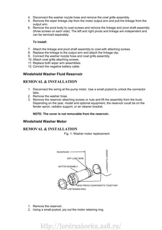
  • 1. 4. Disconnect the washer nozzle hose and remove the cowl grille assembly. 5. Remove the wiper linkage clip from the motor output arm and pull the linkage from the output arm. 6. Remove the pivot body to cowl screws and remove the linkage and pivot shaft assembly (three screws on each side). The left and right pivots and linkage are independent and can be serviced separately. To install: 7. Attach the linkage and pivot shaft assembly to cowl with attaching screws. 8. Replace the linkage to the output arm and attach the linkage clip. 9. Connect the washer nozzle hose and cowl grills assembly. 10. Attach cowl grille attaching screws. 11. Replace both wiper arm assemblies. 12. Connect the negative battery cable. Windshield Washer Fluid Reservoir REMOVAL & INSTALLATION 1. Disconnect the wiring at the pump motor. Use a small prytool to unlock the connector tabs. 2. Remove the washer hose. 3. Remove the reservoir attaching screws or nuts and lift the assembly from the truck. Depending on the year, model and optional equipment, the reservoir could be on the fender apron, radiator support, or air cleaner bracket. NOTE: The cover is not removable from the reservoir. Windshield Washer Motor REMOVAL & INSTALLATION Fig. 1: Washer motor replacement 1. Remove the reservoir. 2. Using a small prytool, pry out the motor retaining ring. http://fordrazborka.zu8.ru/
  • 2. 3. Using pliers, grip one edge of the electrical connector ring and pull the motor, seal and impeller from the reservoir. NOTE: If the seal and impeller come apart from the motor, it can all be re- assembled. To install: 4. Take the time to clean out the reservoir before installing the motor. 5. Coat the seal with a dry lubricant, such as powdered graphite or spray Teflon® . This will aid assembly. 6. Align the small projection on the motor end cap with the slot in the reservoir and install the motor so that the seal seats against the bottom of the motor cavity. 7. Press the retaining ring into position. A 1 in., 12-point socket or length of 1 in. tubing, will do nicely as an installation tool. 8. Install the reservoir and connect the wiring. NOTE: It's not a good idea to run a new motor without filling the reservoir first. Dry-running will damage a new motor. INSTRUMENTS AND SWITCHES Precautions Electronic modules, such as instrument clusters, powertrain controls and sound systems are sensitive to static electricity and can be damaged by static discharges which are below the levels that you can hear "snap'' or detect on your skin. A detectable snap or shock of static electricity is in the 3,000 volt range. Some of these modules can be damaged by a charge of as little as 100 volts. The following are some basic safeguards to avoid static electrical damage: • Leave the replacement module in its original packing until you are ready to install it. • Avoid touching the module connector pins • Avoid placing the module on a non-conductive surface • Use a commercially available static protection kit. These kits contain such things as grounding cords and conductive mats. Instrument Cluster REMOVAL & INSTALLATION Fig. 1: Cluster opening finish panels http://fordrazborka.zu8.ru/
  • 3. 1. Disconnect the negative battery cable. 2. Remove the wiper-washer knob. Use a hook tool to release each knob lock tab. 3. Remove the knob from the headlamp switch. Remove the fog lamp switch knob, if so equipped. 4. Remove the steering column shroud. Care must be taken not to damage the transmission control selector indicator (PRNDL) cable on vehicles equipped with an automatic transmission. 5. On vehicles equipped with an automatic transmission, remove the loop on the indicator cable assembly from the retainer pin. Remove the bracket screw from the cable bracket and slide the bracket out of the slot in the tube. 6. Remove the cluster trim cover. Remove the 4 cluster attaching screws, disconnect the speedometer cable wire connector from the printed circuit, 4x4 indicator light and remove the cluster. 7. Position the cluster at the opening and connect the multiple connector, the speedometer cable and 4x4 indicator light. Install the 4 cluster retaining screws. 8. If so equipped, place the loop on the transmission indicator cable assembly over the retainer on the column. 9. Position the tab on the steering column bracket into the slot on the column. Align and attach the screw. 10. Place the transmission selector lever on the steering column into the DRIVE position. 11. Adjust the slotted bracket so the pin is within the letter band. 12. Install the trim cover. 13. Install the headlamp switch knob. If so equipped, install the fog lamp switch. 14. Install the wiper washer control knobs. 15. Connect the battery cable, and check the operation of all gauges, lights and signals. Tachometer REMOVAL & INSTALLATION 1. Disconnect the negative battery cable. 2. Remove the instrument cluster. 3. Remove the cluster mask and lens. 4. Remove the tachometer by prying the dial away from the cluster back plate. The tachometer is retained by clips. 5. Installation is the reverse of removal. Make sure the clips are properly seated. http://fordrazborka.zu8.ru/
  • 4. Speedometer Cable Core REMOVAL & INSTALLATION Fig. 1: Speedometer driven gear-to-transmission installation — all models Fig. 2: Speedometer cable quick-disconnect NOTE: 1988–96 models equipped with the 4.9L MFI, 5.0L MFI and 5.8L MFI engines have a speed sensor attached to the transmission. This device sends information on vehicle speed to the Engine Management System and Cruise Control System. For replacement of this unit, see the Cruise Control procedures in this section. 1. Reach up behind the cluster and disconnect the cable by depressing the quick disconnect tab and pulling the cable away. 2. Remove the cable from the casing. If the cable is broken, raise the vehicle on a hoist and disconnect the cable from the transmission. 3. Remove the cable from the casing. 4. To remove the casing from the vehicle pull it through the floor pan. http://fordrazborka.zu8.ru/
  • 5. To install: 5. To replace the cable, slide the new cable into the casing and connect it at the transmission. 6. Route the cable through the floor pan and position the grommet in its groove in the floor. 7. Push the cable onto the speedometer head. Speedometer Head REMOVAL & INSTALLATION 1. Remove the instrument cluster. 2. Disconnect the cable from the head. 3. Remove the lens and any surrounding trim. 4. Remove the 2 attaching screws. 5. Installation is the reverse of removal. Place a glob of silicone grease on the end of the cable core prior to connection. Fuel Gauge REMOVAL & INSTALLATION 1. Disconnect the negative battery cable. 2. Remove the instrument cluster. 3. Remove the cluster mask and lens. 4. Remove the 2 nuts attaching the gauge to the cluster back plate. 5. Installation is the reverse of removal. Windshield Wiper Switch REMOVAL & INSTALLATION 1. Disconnect the negative battery cable. 2. Remove the switch knob, bezel nut and bezel. 3. Pull the switch out from under the panel and unplug the wiring. 4. Installation is the reverse of removal. Headlight Switch REMOVAL & INSTALLATION 1. Disconnect the negative battery cable. 2. Depending on the year and model remove the wiper-washer and fog lamp switch knob if they will interfere with the headlight switch knob removal. Check the switch body (behind dash, see Step 3) for a release button. Press in on the button and remove the knob and shaft assembly. If not equipped with a release button, a hook tool may be necessary for knob removal. 3. Remove the steering column shrouds and cluster panel finish panel if they interfere with the required clearance for working behind the dash. 4. Unscrew the switch mounting nut from the front of the dash. Remove the switch from the back of the dash and disconnect the wiring harness. 5. Install in reverse order. LIGHTING http://fordrazborka.zu8.ru/
  • 6. Headlights REMOVAL & INSTALLATION Fig. 1: Twist it counterclockwise Fig. 2: DO NOT touch the headlight bulb glass — if you do, wipe it clean with an alcohol soaked paper towel CAUTION The headlamp bulb contains high pressure halogen gas. The bulb may shatter if scratched or dropped! Hold the bulb by its plastic base only. If you touch the glass portion with your fingers, or if any dirt or oily deposits are found on the glass, it must be wiped clean with an alcohol soaked paper towel. Even the oil from your skin will cause the bulb to burn out prematurely due to hot-spotting. 1. Make sure that the headlight switch is OFF. 2. Raise the hood and find the bulb base protruding from the back of the headlamp assembly 3. Disconnect the wiring by grasping the connector and snapping it rearward firmly. http://fordrazborka.zu8.ru/
  • 7. 4. Rotate the bulb retaining ring counterclockwise (rear view) about 1 ⁄8 turn and slide it off the bulb base. Don't lose it; it's re-usable. 5. Carefully pull the bulb straight out of the headlamp assembly. Don't rotate it during removal. WARNING Don't remove the old bulb until you are ready to immediately replace it! Leaving the headlamp assembly open, without a bulb, will allow foreign matter such as water, dirt, leaves, oil, etc. to enter the housing. This type of contamination will cut down on the amount and direction of light emitted, and eventually cause premature blow-out of the bulb. To install: 6. With the flat side of the bulb base facing upward, insert it into the headlamp assembly. You may have to turn the bulb slightly to align the locating tabs. Once aligned, push the bulb firmly into place until the bulb base contacts the mounting flange in the socket. 7. Place the retaining ring over the bulb base, against the mounting flange and rotate it clockwise to lock it. It should lock against a definite stop when fully engaged. 8. Snap the electrical connector into place. A definite snap will be felt. 9. Turn the headlights on and check that everything works properly. AIMING Fig. 1: Headlamp adjustment points The headlights must be properly aimed to provide the best, safest road illumination. The lights should be checked for proper aim and adjusted as necessary. Certain state and local authorities have requirements for headlight aiming; these should be checked before adjustment is made. Each headlight is adjusted by means of 2 screws located at the 10 o'clock and 3 o'clock positions on the headlight underneath the trim ring. Always bring each beam into final position by turning the adjusting screws clockwise so that the headlight will be held against the tension springs when the operation is completed. Headlight adjustment may be temporarily made using a wall, as described below, or on the rear of another vehicle. When adjusted, the lights should not glare in oncoming car or truck windshields, nor should they illuminate the passenger's compartment of vehicles driving in front http://fordrazborka.zu8.ru/
  • 8. of you. These adjustments are rough and should always be fine-tuned by a repair shop which is equipped with headlight aiming tools. Improper adjustments may be both dangerous and illegal. Before making any headlight adjustments, perform the following preparatory steps: 1. Make sure all tires are properly inflated. 2. Take into consideration any faulty wheel alignment or improper rear axle tracking. 3. Make sure there is no load in the truck other than the driver. 4. The truck's fuel tank should be about half full. 5. Make sure all lenses are clean. To adjust: 6. Park the truck on a level surface, with the fuel tank no more than 1 ⁄2 full and with the vehicle empty of all extra cargo (unless normally carried). The vehicle should be facing a wall which is no less than 6 feet (1.8m) high and 12 feet (3.7m) wide. The front of the vehicle should be about 25 feet (7.6m) from the wall. 7. If this is be performed outdoors, it is advisable to wait until dusk in order to properly see the headlight beams on the wall. If done in a garage, darken the area around the wall as much as possible by closing shades or hanging cloth over the windows. 8. Turn the headlights ON and mark the wall at the center of each light's low beam, then switch on the "brights'' and mark the center of each light's high beam. A short length of masking tape which is visible from the front of the truck may be used. Although marking all 4 positions is advisable, marking 1 position from each light should be sufficient. 9. If neither beam on one side of the vehicle is working, park another like-sized truck in the exact spot where the truck was and mark the beams using the same side light on that truck. Then switch the trucks so the truck being worked on is back in the original spot. The truck must be parked no closer to or farther away from the wall than the second vehicle. 10. Perform the necessary repairs, but make sure the truck is not moved or is returned to the exact spot from which the lights were marked. Turn the headlights ON and adjust the beams to match the marks on the wall. 11. Have the headlight adjustment checked as soon as possible by a reputable repair shop. Signal and Marker Lights REMOVAL & INSTALLATION Front Turn Signal and Parking Lights 1. Remove the headlamp assembly attaching screws. 2. Pull the headlamp assembly out and disconnect the parking lamp socket from the headlamp body. 3. Replace the bulb. 4. Installation is the reverse of removal. Rear Turn Signal, Brake and Parking Lights STYLE SIDE PICK-UPS AND BRONCO Fig. 1: Remove the screws from the rear of the rear light lens http://fordrazborka.zu8.ru/
  • 9. Fig. 2: Lower the tailgate, then remove the retaining screw from the rear lens Fig. 3: Twist the bulb socket counterclockwise, then pull it from the light assembly http://fordrazborka.zu8.ru/
  • 10. Fig. 4: Pull the affected bulb from the socket and replace it with the correct type bulb 1. Remove the screws that attach the combination light lens assembly and remove the lens. 2. Turn the affected bulb socket counterclockwise to remove the bulb; clockwise to install a new bulb. FLARE SIDE PICK-UPS Fig. 5: Roof marker lamps for all models http://fordrazborka.zu8.ru/
  • 11. The bulbs can be replaced by removing the lens (4 screws). To replace the lamp assembly, remove the 3 nuts from the mounting studs, disconnect the wiring inside the frame rail, unhook the wiring from the retaining clip, pull out the wires and remove the lamp assembly. High-mount Brake Light Fig. 6: Remove the retaining screws from the hi-mount brake light Fig. 7: Turn the light bulb socket to disengage it from the light assembly http://fordrazborka.zu8.ru/
  • 12. Fig. 8: Pull out the bulb from the socket — always replace it with the specified bulb 1. Remove the 2 screws that retain the hi-mount light. 2. Pull the rear hi-mount light away from the top. 3. To remove the bulb, disconnect the socket from the light assembly, then pull out the bulb. 4. To remove the light assembly, disconnect the wiring from the light, then remove the light. 5. Reverse the removal procedure to install. Dome/ Map Light BRONCO MODELS 1. Carefully pry the dome lamp lens, at the corners, from the housing. 2. Remove the 2 screws attaching the map lamp lens housing to the lamp base and remove the bulbs. The lamp base is retained to the roof by 4 screws. 3. Installation is the reverse of removal. http://fordrazborka.zu8.ru/
  • 13. F-150, F-250, F-350 and F-SUPER DUTY MODELS 1. To replace the bulb, snap the lens out of the lamp body and remove the bulb. 2. To remove the lamp body, remove the 4 retaining screws. 3. Installation is the reverse of removal. Cargo Lamp F-150/250/350 AND SUPER-DUTY MODELS Remove the 2 lamp retaining screws and remove the lamp. Remove the bulb from the lamp. Installation is the reverse of removal. BRONCO MODELS Carefully unsnap the lamp from the side of the truck, disconnect the wiring and remove the bulb. Installation is the reverse of removal. Fig. 9: Remove the lens to access the dome light mounting screws — F-150 shown, others similar Fig. 10: Simply pull the bulb from its connections as demonstrated http://fordrazborka.zu8.ru/
  • 14. TRAILER WIRING Wiring the vehicle for towing is fairly easy. There are a number of good wiring kits available and these should be used, rather than trying to design your own. All trailers will need brake lights and turn signals as well as tail lights and side marker lights. Most areas require extra marker lights for overly wide trailers. Also, most areas have recently required back-up lights for trailers, and most trailer manufacturers have been building trailers with back-up lights for several years. Additionally, some Class I, most Class II and just about all Class III trailers will have electric brakes. Add to this number an accessories wire, to operate trailer internal equipment or to charge the trailer's battery, and you can have as many as seven wires in the harness. Determine the equipment on your trailer and buy the wiring kit necessary. The kit will contain all the wires needed, plus a plug adapter set which includes the female plug, mounted on the bumper or hitch, and the male plug, wired into, or plugged into the trailer harness. When installing the kit, follow the manufacturer's instructions. The color coding of the wires is usually standard throughout the industry. One point to note: some domestic vehicles, and most imported vehicles, have separate turn signals. On most domestic vehicles, the brake lights and rear turn signals operate with the same bulb. For those vehicles with separate turn signals, you can purchase an isolation unit so that the brake lights won't blink whenever the turn signals are operated, or, you can go to your local electronics supply house and buy 4 diodes to wire in series with the brake and turn signal bulbs. Diodes will isolate the brake and turn signals. The choice is yours. The isolation units are simple and quick to install, but far more expensive than the diodes. The diodes, however, require more work to install properly, since they require the cutting of each bulb's wire and soldering in place of the diode. One, final point, the best kits are those with a spring loaded cover on the vehicle mounted socket. This cover prevents dirt and moisture from corroding the terminals. Never let the vehicle socket hang loosely; always mount it securely to the bumper or hitch. CIRCUIT PROTECTION http://fordrazborka.zu8.ru/
  • 15. Fuses Fig. 1: Remove the cover from the fuse panel Fig. 2: Use only the fuses specified for the circuit Fig. 3: Firewall-mounted fuse box, turn signal and hazard flashers http://fordrazborka.zu8.ru/
  • 16. Fig. 4: Instrument panel-mounted fuse box On earlier models, the fuse panel is located on the firewall above the driver's left foot. On later models, the fuse panel is located on the underside of the instrument panel, covered with an access door. Circuit Breakers Two circuits are protected by circuit breakers located in the fuse panel: the power windows (20 amp) or power windows and Shift-On-The-Fly (30 amp) and the power door locks (30 amp). The breakers are self-resetting. Turn Signal and Hazard Flasher Locations Both the turn signal flasher and the hazard warning flasher are mounted on the fuse panel. The turn signal flasher is mounted on the front of the fuse panel, and the hazard warning flasher is mounted on the rear of the fuse panel. http://fordrazborka.zu8.ru/
  • 17. Fuse Link The fuse link is a short length of special, Hypalon (high temperature) insulated wire, integral with the engine compartment wiring harness and should not be confused with standard wire. It is several wire gauges smaller than the circuit which it protects. Under no circumstances should a fuse link replacement repair be made using a length of standard wire cut from bulk stock or from another wiring harness. To repair any blown fuse link use the following procedure: 1. Determine which circuit is damaged, its location and the cause of the open fuse link. If the damaged fuse link is one of three fed by a common No. 10 or 12 gauge feed wire, determine the specific affected circuit. 2. Disconnect the negative battery cable. 3. Cut the damaged fuse link from the wiring harness and discard it. If the fuse link is one of 3 circuits fed by a single feed wire, cut it out of the harness at each splice end and discard it. 4. Identify and procure the proper fuse link and butt connectors for attaching the fuse link to the harness. 5. To repair any fuse link in a 3-link group with one feed: A. After cutting the open link out of the harness, cut each of the remaining undamaged fuse links close to the feed wire weld. B. Strip approximately 1 ⁄2 in. (13mm) of insulation from the detached ends of the 2 good fuse links. Then insert 2 wire ends into one end of a butt connector and carefully push one stripped end of the replacement fuse link into the same end of the butt connector and crimp all three firmly together. NOTE: Care must be taken when fitting the 3 fuse links into the butt connector as the internal diameter is a snug it for 3 wires. Make sure to use a proper crimping tool. Pliers, side cutters, etc. will not apply the proper crimp to retain the wires and withstand a pull test. C. After crimping the butt connector to the 3 fuse links, cut the weld portion from the feed wire and strip approximately 1 ⁄2 in. (13mm) of insulation from the cut end. Insert the stripped end into the open end of the butt connector and crimp very firmly. D. To attach the remaining end of the replacement fuse link, strip approximately 1 ⁄2 in. (13mm) of insulation from the wire end of the circuit from which the blown fuse link was removed, and firmly crimp a butt connector or equivalent to the stripped wire. Then, insert the end of the replacement link into the other end of the butt connector and crimp firmly. E. Using rosin core solder with a consistency of 60 percent tin and 40 percent lead, solder the connectors and the wires at the repairs and insulate with electrical tape. 6. To replace any fuse link on a single circuit in a harness, cut out the damaged portion, strip approximately 1 ⁄2 in. (13mm) of insulation from the 2 wire ends and attach the appropriate replacement fuse link to the stripped wire ends with 2 proper size butt connectors. Solder the connectors and wires and insulate the tape. 7. To repair any fuse link which has an eyelet terminal on one end such as the charging circuit, cut off the open fuse link behind the weld, strip approximately 1 ⁄2 in. (13mm) of insulation from the cut end and attach the appropriate new eyelet fuse link to the cut stripped wire with an appropriate size butt connector. Solder the connectors and wires at the repair and insulate with tape. 8. Connect the negative battery cable to the battery and test the system for proper operation. http://fordrazborka.zu8.ru/
  • 18. NOTE: Do not mistake a resistor wire for a fuse link. The resistor wire is generally longer and has print stating, "Resistor: don't cut or splice." WIRING DIAGRAMS Fig. 1: Sample diagram — how to read and interpret wiring Fig. 2: Common wiring diagram symbols Fig. 3: Engine wiring — 1987–89 F-Series and Bronco 5.0L (VIN N), 1988–89 F-Series and Bronco 5.8L (VIN H) and 1988–89 F-Series Pick-up 7.5L (VIN G) engines Fig. 4: Engine wiring — 1987 F-Series Pick-up 7.5L (VIN G), 1987 F-Series and Bronco 5.8L (VIN H) engines Fig. 5: Engine wiring — 1987–89 F-Series Pick-up 7.3L (VIN M) diesel engine Fig. 6: Engine wiring — 1987–88 F-Series Pick-up 4.9L (VIN Y) engine Fig. 7: Engine wiring — 1989 F-Series Pick-up 4.9L (VIN Y) engine Fig. 8: Engine wiring — 1990 F-Series Pick-up 7.5L (VIN G) engine Fig. 9: Engine wiring — 1990 F-Series Pick-up 4.9L (VIN Y) engine Fig. 10: Engine wiring — 1991 F-Series Pick-up 7.5L (VIN G) engine Fig. 11: Engine wiring — 1991 F-Series Pick-up 4.9L (VIN Y) engine Fig. 12: Engine wiring — 1990 F-Series and Bronco 5.0L (VIN N) and 5.8L (VIN H) Fig. 13: Engine wiring — 1991 F-Series and Bronco 5.0L (VIN N) and 5.8L (VIN H) Fig. 14: Engine wiring — 1990–93 F-Series Pick-up 7.3L (VIN M) diesel engine Fig. 15: Engine wiring — 1994–95 F-Series and Bronco 5.0L Auto Transmission (VIN N) engine Fig. 16: Engine wiring — 1994–95 F-Series and Bronco 5.0L Manual Transmission (VIN N) engine Fig. 17: Engine wiring — 1994 F-Series Pick-up 7.3L (VIN M) diesel engine Fig. 18: Engine wiring — 1992–94 F-Series 4.9L (VIN Y) and 1995 4.9L Federal (VIN Y) engines http://fordrazborka.zu8.ru/
  • 19. Fig. 19: Engine wiring — 1992–93 F-Series and Bronco 5.0L (VIN N), 1992–94 F-Series and Bronco 5.8L (VIN H) and 1995 F-Series and Bronco 5.8L (VIN H) engine Fig. 20: Engine wiring — 1995 F-Series 4.9L California (VIN Y) engine Fig. 21: Engine wiring — 1995 F-Series and Bronco 5.8L California (VIN H) engine Fig. 22: Engine wiring — 1992–95 F-Series 7.5L (VIN G), 1996 F-Series 7.5L Federal (VIN G) and 1996 F-Series Pick- up 5.8L (VIN H over 8500 GVW) engines Fig. 23: Engine wiring — 1994–96 F-Series Pick-up 7.3L (VIN F) turbo diesel engines Fig. 24: Engine wiring — 1996 F-Series and Bronco 5.0L (VIN N), 5.8L (VIN H under 8500 GVW), 7.5L California (VIN G) engines Fig. 25: Engine wiring — 1996 F-Series 4.9L (VIN Y) engine Fig. 26: Chassis wiring — 1987–89 F-Series and Bronco Fig. 27: Chassis wiring — 1987–91 F-Series and Bronco Fig. 28: Chassis wiring — 1990–91 F-Series and Bronco Fig. 29: Chassis wiring — 1992 F-Series and Bronco Fig. 30: Chassis wiring — 1992–96 F-Series and Bronco Fig. 31: Chassis wiring — 1993–96 F-Series and Bronco Fig. 32: TROUBLESHOOTING BASIC TURN SIGNAL AND FLASHER PROBLEMS DRIVE TRAIN MANUAL TRANSMISSION Adjustments LINKAGE 3.03 Three Speed Fig. 1: Aligning the shift rods at the steering column http://fordrazborka.zu8.ru/
  • 20. Fig. 2: Shift rod linkage adjustment position — E–150 to E– 350 shown A column shift is used with this transmission. 1. Install a 3 ⁄16 (4.76mm) diameter gauge pin, through the locating hole in the steering column shift levers and the plastic spacer. 2. Locate the levers in the center of the steering column window. 3. Loosen nuts A and B and position the transmission shift levers in the Neutral detents. 4. Tighten nuts A and B to 12–18 ft. lbs. (17–24 Nm), using care to prevent motion between the stud and rod. 5. Remove the gauge pin. 6. Check the linkage operation. Make sure there is no interference between the steering column levers and window when shifting into gear. NOTE: Always use new retaining rings and new insulators when making transmission control adjustments. New retaining rings should also be used whenever the existing retaining rings are removed. The rings as well as the plastic http://fordrazborka.zu8.ru/
  • 21. grommets where the shift rods are attached, should be replaced whenever excessive wear or looseness is noted during normal vehicle inspections. Ford TOD 4-Speed Overdrive Fig. 3: Shifter mounting and linkage A floor mounted shift is used with this transmission. 1. Attach the shift rods in the levers. 2. Rotate the output shaft to determine that the transmission is in Neutral. 3. Insert a alignment pin into the shift control assembly alignment hole. 4. Attach the slotted end of the shift rods over the flats of the studs in the shift control assembly. 5. Install the locknuts and tighten the locknuts to 15–20 ft. lbs. (21–27 Nm). Remove the alignment pin. CLUTCH SWITCH Fig. 1: Adjustable type clutch interlock switch http://fordrazborka.zu8.ru/
  • 22. Fig. 2: Non-adjustable type clutch interlock switch The clutch interlock switch is used on all truck models, however this switch is adjustable in some models up to 1991. On vehicles after 1991 the switch in non-adjustable. If the switch does not function it must be replaced. 1. Disconnect the negative battery cable. 2. If the adjusting clip is out of position on the rod, remove both halves of the clip. 3. Position both halves of the clip closer to the switch and snap the clips together on the rod. 4. Depress the clutch pedal to the floor to adjust the switch. 5. Connect the negative battery cable. 6. Check switch function by attempting to start the engine without depressing the clutch pedal, the engine should not start. The engine should start when the clutch pedal is depress. CAUTION Make sure the transmission is in Neutral and the hand brake is applied when attempting to start the vehicle without the clutch pedal depressed. Shift Linkage REMOVAL & INSTALLATION 3.03 Three Speed Transmission NOTE: Most column mounted shift lever assemblies incorporate a plastic grommet in each lever arm. A special tool T67P–7341 or equivalent is required to install the grommet in the shaft lever and to install the shaft linkage rod into the grommet. 1. To remove the rod end connected to the shift column, place the lower jaw of the tool between the shift lever and the shift rod. If working in limited space use tool T84P-341-A or equivalent. 2. Position the stop pin against the end of the shift rod and force the rod out of the grommet. http://fordrazborka.zu8.ru/
  • 23. 3. The grommet is removed from the lever by cutting off the large shoulder of the grommet. 4. Remove the grommet from the lever by pushing it out of the lever. 5. Disconnect the rod at the transmission manual shift lever by removing the attaching nut and remove the linkage. To install: 6. Prior to installing a new grommet, adjust the stop pin if necessary to properly install the grommet. Coat the outside of the grommet with a Multipurpose Long Life lubricant. Then place the grommet on the stop pin and force it into the shift lever hole. Turn the grommet several times to be sure it is properly seated. 7. Re-adjust the stop pin to a length which is sufficient to install the shift rod into the grommet. If the pin height is not adjusted, the shaft rod may be pushed too far through the grommet, causing damage to the grommet retaining lip. 8. With the pin height properly adjusted, position the shift rod on the tool and force the rod into the grommet until the groove in the rod seats on the inner retaining lip of the grommet. 9. Install the shift rods to the correct shift lever and install the retaining nuts. Do not tighten. 10. Adjust the shift linkage as described in this section. 4-Speed Overdrive Transmission Fig. 1: Exploded view of the shifter assembly 1. Raise the vehicle and safely support it with jackstands. NOTE: The shift linkage consist of 3 shift rods connected between the shifter and transmission. If all shift rods are being removed, matchmark each rod to the lever it is being removed from. This will insure proper installation location of each rod. 2. Disconnect the 3 shift rods at the transmission end by removing the retainer clip and washer then pull each rod free from the shift lever. A bushing should be inside the eye of the shift linkage. Replace this bushing if required. 3. Disconnect the shift linkage at the shifter end by removing the locknuts and remove the shift linkage from the vehicle. To install: http://fordrazborka.zu8.ru/
  • 24. 4. Install the shift rods one at a time to the correct locations marked. 5. Replace the bushing at the end of the rod (transmission side) as required. 6. Connect the rod to the transmission shift lever and install the washer and retainer clip. 7. Connect the rod to the shifter and install the locknut, but do not tighten. Adjust the shift linkage. See the above procedure. 8. Remove the jackstands and lower the vehicle. Shift Handle REMOVAL & INSTALLATION Borg Warner T-18 and T-19; New Process 435 4-Speed Overdrive NOTE: Remove the shift ball only if the shift ball, boot or lever is the be replaced. If either the ball, boot or lever is not being replaced, remove the ball, boot and lever as an assembly. 1. Disconnect the negative battery cable. 2. Remove the plastic insert from the shift ball. Warm the ball with a heat gun to 140–180°F (60–82°C) knock the ball off the lever with a block of wood and a hammer taking care not damage the finish on the shift lever. 3. Remove the rubber boot and floor pan cover. 4. Except 4 speed overdrive transmission, shift the unit into second gear, remove the lockpin and remove the shift lever from the shifter housing. 5. Vehicles with 4 speed overdrive transmission, shift the unit into second gear. Depress the retainer clip on the end of the shift lever and remove the shift lever from the housing. To install: 6. Except 4 speed overdrive transmission, install the shift lever in the shifter housing, making sure that the slot in the lever aligns with the tab in the housing. Install the lockpin. 7. Vehicles with 4 speed overdrive transmission, install the shift lever in the shifter housing, making sure that the retaining clip on the lever aligns with the slot in the housing and snaps into place. Install the lockpin. 8. Install the rubber boot and floor pan cover. 9. Warm the ball with a heat gun to 140–180°F (60–82°C) and tap the ball on the lever with a 7 ⁄16 inch socket and mallet. Install the plastic shift pattern insert. 10. Vehicles with 4 speed overdrive transmission, the shifter is removed by depressing the retainer clip on the end of the shift lever. 11. Connect the negative battery cable. Ford TOD 4-Speed Overdrive NOTE: Remove the shift ball only if the shift ball, boot or lever is to be replaced. If neither the ball, boot nor lever is not being replaced, remove the ball, boot and lever as an assembly. 1. Disconnect the negative battery cable. 2. Remove the plastic insert from the shift ball. Warm the ball with a heat gun to 140–180°F (60–82°C) knock the ball off the lever with a block of wood and a hammer taking care not damage the finish on the shift lever. 3. Remove the screws retaining the boot and pad to the floor plate. 4. Shift the transmission into Neutral. 5. Remove the boot from the cap. Place an oil filter wrench around the gearshift housing cap and twist off the cap. http://fordrazborka.zu8.ru/
  • 25. WARNING Do not twist the gearshift housing cap by hand. Due to the clearance between the floor plate and cap, the hands may be cut. 6. Remove the shift lever from the transmission. To install: 7. Install the shift lever in the gearshift housing, making sure that the slots in the lever aligns with the pins in the housing. 8. Install the rubber boot and pad. Install the screws retaining the boot and pad to the floor plate. 9. Warm the ball with a heat gun to 140–180°F (60–82°C) and tap the ball on the lever with a 7 ⁄16 inch socket and mallet. Install the plastic shift pattern insert. 10. Connect the negative battery cable. ZF S5–42 and ZF S5–47 1. Disconnect the negative battery cable. 2. Remove the shifter boot and bezel assembly from the transmission opening cover. 3. Remove the 2 bolts retaining the upper shift lever to the lower shift lever and remove the upper shift lever. To install: 4. Install the upper shift lever to the lower lever and install the retaining bolts. Tighten 16– 24 ft. lbs. (22–33 Nm). 5. Install shifter boot and bezel assembly to the transmission opening cover. 6. Install the shift ball on the upper shifter if removed. 7. Connect the negative battery cable. Mazda M50D 5-Speed Fig. 1: Removing the shifter boot retaining screws Fig. 2: Pull the boot up over the shift lever, exposing the sound deadening material http://fordrazborka.zu8.ru/
  • 26. Fig. 3: Examine the condition of the boot and sound deadening material Fig. 4: If removing the shift lever from the stub shaft, install and tighten the locknut from the opposite side Fig. 5: The shift lever can be removed from the stub shaft by removing the shift lever-to-stub shaft bolt Fig. 6: To remove the shift lever and stub shaft together, remove the shift dust cover retaining screws http://fordrazborka.zu8.ru/
  • 27. Fig. 7: Removing the shift lever assembly with the stub shaft 1. Disconnect the negative battery cable. 2. Shift the transmission into Neutral 3. Remove the carpet or floor mats. 4. Remove the shifter boot retainer screws and slide the boot up the shift lever shaft. 5. Remove the shift lever retaining bolt locknut. 6. Remove the shift lever retaining bolt by placing the locknut on the opposite end of the bolt and tightening to loosen the bolt. 7. The shifter may be removed either by removing the bolt retaining the shifter to the shifter stub and then pulling the shifter off or by removing the screws retaining the shifter to the shift housing and remove the shifter and boot assembly. To install: 8. If shifter was removed from the shifter stub shaft, install the retaining bolt in the shift lever hole so that the flat aligns with the mating flat on the transmission stub shaft. Push the bolt fully into position. Install the nut and tighten to 12–18 ft. lbs. (16–24 Nm). 9. If the shifter and stub shaft were removed together, position the shifter lever into the shift housing aligning the end of the shifter with the slot in the transmission. Install the retaining screws and tighten to 6–8 ft. lbs. (8–11 Nm). 10. Slide the gearshift boot and sound deadening material into position on the gearshift lever and housing, then install the retaining screws. 11. Install the Isolator pan assembly. Install the floor pan cover and floor carpet it removed. 12. Connect the negative battery cable. http://fordrazborka.zu8.ru/
  • 28. Back-up Light Switch REMOVAL & INSTALLATION Fig. 1: Typical back-up lamp switch located — mounted on the transmission 3.03 3-Speed The back-up light switch is located on the transmission assembly. 1. Disconnect the negative battery cable. 2. Raise and support the vehicle safely with jackstands. 3. Disengage the harness from the back-up light switch. 4. Using a suitable wrench or ratchet/socket, remove the switch from the transmission. To install: 5. Tread the back-up light switch into the transmission. Tighten the switch 8–12 ft. lbs. (11– 16 Nm). 6. Engage the harness to the switch. 7. Remove the jackstands and lower the vehicle 8. Connect the negative battery cable. Check switch operation. 4-Speed Overdrive Transmission The Back-up light switch is mounted on to the floor shift assembly on the transmission extension housing on F150–F250 or on a bracket attached to the transmission case for E150–E350 vehicles. 1. Disconnect the negative battery cable. 2. Place the transmission shift lever in any gear except Reverse. 3. Raise and support the vehicle safely with jackstands. 4. Disengage the electrical connector from the switch. 5. Using a suitable wrench or ratchet/socket, remove the switch from the shifter housing. To install: http://fordrazborka.zu8.ru/
  • 29. 6. Install the back-up light switch into the floor shift assembly or to the transmission case. 7. Engage the harness to the switch. 8. Remove the jackstands and lower the vehicle 9. Connect the negative battery cable. Check switch operation. Borg Warner T-18 and T-19; New Process 435; TOD 4 Speed Overdrive Fig. 2: Back-up light switch — located on the shifter housing The back-up light switch is located at the rear of the gear shift housing cover. 1. Disconnect the negative battery cable. 2. Raise and support the vehicle safely with jackstands. 3. Disengage the harness from the back-up light switch. 4. Using a suitable wrench or ratchet/socket, remove the switch from the transmission. To install: 5. Tread the back-up light switch into the transmission. Tighten the switch 15–25 ft. lbs. (20–47 Nm) for T–18 and T–19 or 20–30 ft. lbs. (28–54 Nm) for NP 435 transmission. 6. Engage the harness to the switch. 7. Remove the jackstands and lower the vehicle 8. Connect the negative battery cable. Check switch operation. Extension Housing Seal REMOVAL & INSTALLATION 2WD Models Fig. 1: Removing the extension housing seal http://fordrazborka.zu8.ru/
  • 30. Fig. 2: Always replace the old seal with a new one Fig. 3: Using a special tool and mallet, install the new seal The extension seal on 2WD drive vehicles is located at the rear of the transmission case. 1. Raise and support the vehicle safely. 2. Drain the transmission of lubricant. 3. Matchmark the driveshaft to the yoke for reassembly and remove the driveshaft. 4. Remove the old seal using a seal puller or appropriate prytool. To install: http://fordrazborka.zu8.ru/
  • 31. 5. Install a new seal, coated with sealing compound, using an appropriate seal installation tool. NOTE: Tool J-35582 or equivalent is recommended for AX4/5/15 transmissions. Tool J-21426 or equivalent is recommended for Warner T4/5 transmissions. 6. Install the driveshaft, making certain to align the matchmark. 7. Fill the transmission to the level of the fill plug hole. Install the plug and lower the vehicle. 4WD Models The extension seal on 4WD drive vehicles is located at the rear of the transfer case. Transmission Assembly REMOVAL & INSTALLATION Fig. 1: Before removing the crossmember bolt, always have the transmission supported Fig. 2: With the transmission jack in place, remove the frame- to-crossmember bolts http://fordrazborka.zu8.ru/
  • 32. Fig. 3: Removing the frame-to-crossmember bolts on the opposite side Fig. 4: Disengage any connectors at the transmission http://fordrazborka.zu8.ru/
  • 33. Fig. 5: With the transmission jack in place, remove the transmission mount bolts Fig. 6: Remove the bell housing bolts http://fordrazborka.zu8.ru/
  • 34. Fig. 7: Carefully pull the transmission away from the clutch assembly until the input shaft is completely clear CAUTION The clutch driven disc may contain asbestos, which has been determined to be a cancer causing agent. Never clean clutch surfaces with compressed air! Avoid inhaling any dust from any clutch surface! When cleaning clutch surfaces, use a commercially available brake cleaning fluid. 3.03 3-Speed 1. Disconnect the negative battery cable. 2. Raise the vehicle and safely support it with jackstands. 3. Support the engine with a jack and wood under the oil pan. 4. Drain the transmission. 5. Disconnect the gear shift linkage at the transmission. 6. Disconnect the speedometer cable. Disengage the harness from the back-up light switch. 7. Remove the driveshaft. http://fordrazborka.zu8.ru/
  • 35. 8. Raise the transmission just enough to remove the rear support, insulator and retainer assembly. 9. Position a transmission jack under the transmission and secure it to the jack. 10. Remove the transmission-to-flywheel housing attaching bolts. 11. Move the transmission to the rear until the input shaft clears the clutch housing. 12. Carefully lower the transmission from the vehicle. To install: NOTE: Prior to installing the transmission, apply a light film of a Multi-Purpose Long-life lubricant to the release bearing inner hub surfaces, release lever fulcrum, fork and transmission front bearing retainer. Be sure to exercise care to avoid contaminating the clutch disc with grease. 13. Secure the transmission on the transmission jack. 14. Raise the transmission until the input shaft splines are in-line with the clutch disc splines. The clutch release bearing and hub must be properly positioned in the release lever fork. 15. Install a guide stud in each lower flywheel housing-to-transmission case mounting bolt holes and align the splines on the input shaft with the spines on the clutch disc. 16. Slide the transmission forward on the guide studs until it contacts the clutch housing. 17. Install the 2 transmission-to-flywheel housing upper mounting bolts. Remove the 2 guide studs and install the lower mounting bolts. Tighten the 4 mounting bolts to 42–50 ft. lbs. (57–67 Nm). 18. Install the rear support, insulator and retainer assembly and tighten the attaching bolts and nuts to 48–65 ft. lbs. (65–88 Nm). 19. Remove the transmission jack and engine jack. 20. Connect the speedometer cable and the driven gear. 21. Install the driveshaft. 22. Connect each shift rod to its respective lever on the transmission. 23. Install the lower extension housing-to-rear mount bolts and tighten to 60–80 ft. lbs. (82– 108 Nm). Install the rear mount-to-frame nuts to 50–70 ft. lbs. (68–94 Nm). 24. Adjust the shift linkage as required. 25. Connect the wiring to the back-up light switch. Warner T-18, T-19A, T-19C 4-Speed 2-WHEEL DRIVE 1. Remove the rubber boot, floor mat, and the body floor pan cover. 2. Remove the gearshift lever, shift ball and boot as an assembly. 3. Raise the vehicle and support it with jackstands. 4. Drain the transmission. 5. Remove the driveshaft. 6. Disconnect the speedometer cable. 7. Remove the crossmember-to-transmission bolts. 8. Secure the transmission to a transmission jack. 9. Remove the crossmember. 10. Remove the 4 transmission-to-bell housing bolts, roll the transmission rearward and remove it. To install: NOTE: You can make installation a lot easier if you fabricate 2 guide pins, made by cutting the heads off of 2 long bolts. These guide pins are inserted into the upper bolt holes in the back of the bell housing and serve to align the bolt holes. http://fordrazborka.zu8.ru/
  • 36. 11. Raise the transmission and roll it forward using the guide pins to align the bolt holes. Turn the output shaft by hand to align the input shaft splines with the clutch. 12. Install the 2 lower bolts and snug them down. 13. Remove the guide pins and install the 2 remaining bolts. Torque all 4 bolts to 50 ft. lbs. (68 Nm). 14. Install the crossmember. Crossmember-to-frame bolt torque is 55 ft. lbs. (75 Nm). 15. Remove the transmission jack. 16. Install the Crossmember-to-transmission bolts. Tighten the bolts to 50 ft. lbs. (68 Nm). 17. Connect the speedometer cable. 18. Install the driveshaft. 19. Install the drain plug and fill the transmission. Drain plug torque is 50 ft. lbs. (68 Nm). 20. Lower the vehicle. 21. Install the gearshift lever, shift ball and boot as an assembly. 22. Install the body floor pan cover, floor mat, and the rubber boot. 4-WHEEL DRIVE 1. Remove the rubber boot, floor mat, and the body floor pan cover. Remove the gearshift lever. Remove the weather pad. 2. Remove the transfer case shift lever, shift ball and boot as an assembly. 3. Disconnect the back-up light switch at the rear of the gearshift housing cover. 4. Raise the vehicle and support it with jackstands. Remove the drain and fill plugs and drain the lubricant. 5. Position a transmission jack under the transfer case and disconnect the speedometer cable. 6. Matchmark the flanges and disconnect the rear driveshaft from the transfer case. Wire it up and out of the way. 7. Matchmark and disconnect the front driveshaft at the transfer case. Wire it up and out of the way. 8. Remove the shift link from the transfer case. 9. Unbolt the transfer case from the transmission (6 bolts) and lower the transfer case from the vehicle. 10. Position the transmission jack under the transmission. 11. Remove the 8 rear transmission support-to-transmission bolts. 12. Remove the rear transmission support. 13. Remove the 4 transmission-to-clutch housing attaching bolts. 14. Move the transmission to the rear until the input shaft clears the flywheel housing and lower the transmission. To install: NOTE: You can make installation a lot easier if you fabricate 2 guide pins, made by cutting the heads off of 2 long bolts. These guide pins are inserted into the upper bolt holes in the back of the bell housing and serve to align the bolt holes. 15. Before installing the transmission, apply a light film of grease to the inner hub surface of the clutch release bearing, the release lever fulcrum and the front bearing retainer of the transmission. Do not apply excessive grease because it will fly off onto the clutch disc. 16. Install the transmission in the reverse order of removal. It may be necessary to turn the output shaft with the transmission in gear to align the input shaft splines with the splines in the clutch disc. Fill the transmission with SAE 80W/90 lubricant if it was drained. The transfer case is filled with Dexron® II ATF. Observe the following torque specifications: o Back-up light switch: 25 ft. lbs. (34 Nm) o Transmission-to-clutch housing bolts: 65 ft. lbs. (88 Nm) o Transfer case-to-transmission: 40 ft. lbs. (54 Nm) o Drain plug: 50 ft. lbs. (68 Nm) o Fill plug: 50 ft. lbs. (68 Nm) http://fordrazborka.zu8.ru/
  • 37. o Transmission to rear support: 80 ft. lbs. (108 Nm) o Rear support-to-frame: 55 ft. lbs. (75 Nm) New Process 435 4-Speed 2-WHEEL DRIVE 1. Remove the floor mat. 2. Remove the shift lever boot. 3. Remove the floor pan, transmission cover plate, and weather pad. It may be necessary to remove the seat assembly. 4. Remove the shift lever and knob by first removing the inner cap using tool T73T–7220– A, or equivalent. Then, remove the spring seat and spring. Remove the shift lever from the housing. 5. Disconnect the back-up light switch located in the left side of the gearshift housing cover. 6. Raise the vehicle and place jackstands under the frame to support it. Place a transmission jack under the transmission and disconnect the speedometer cable. 7. Matchmark and disconnect the driveshaft. 8. Remove the transmission rear support. 9. Remove the transmission-to-flywheel housing attaching bolts, slide the transmission rearward until the input shaft clears the flywheel housing and lower it out from under the truck. 10. Before installing the transmission, apply a light film of grease of the inner hub surface of the clutch release bearing, release lever fulcrum and fork, and the front bearing retainer of the transmission. Do not apply excessive grease because if will fly off and contaminate the clutch disc. 11. Install the transmission in the reverse order of removal. It may be necessary to turn the output shaft with the transmission in gear to align the input shaft splines with the splines in the clutch disc. The front bearing retainer is installed through the clutch release bearing. Observe the following torques: o Transmission-to-clutch housing bolts: 65 ft. lbs. (88 Nm) o Back-up light switch: 25 ft. lbs. (34 Nm) o Drain and fill plugs: 30 ft. lbs. (41 Nm) o Transmission-to-support: 80 ft. lbs. (108 Nm) o Support-to-frame: 55 ft. lbs. (75 Nm) 4-WHEEL DRIVE 1. Remove the transmission lever rubber boot and floor mat. 2. Remove the transfer case shift lever, boot and ball as an assembly. 3. Remove the floor pan, transmission cover plate, and weather pad. It may be necessary to remove the seat assembly. 4. Remove the shift lever and knob by first removing the inner cap using tool T73T–7220– A, or equivalent. Then, remove the spring seat and spring. Remove the shift lever from the housing. 5. Disconnect the back-up light switch located in the left side of the gearshift housing cover. 6. Raise the vehicle and place jackstands under the frame to support it. Place a transmission jack under the transfer case and disconnect the speedometer cable. 7. Drain the transfer case. 8. Matchmark and disconnect the front driveshaft from the transfer case. Wire is up out of the way. 9. Matchmark and disconnect the rear driveshaft from the transfer case. Wire it up out of the way. 10. Disconnect the shift link from the transfer case. 11. Remove the 3 bolts securing the transfer case to the support bracket. 12. Remove the 6 bolts securing the transfer case to the transmission. 13. Lower the transfer case from the truck. http://fordrazborka.zu8.ru/
  • 38. 14. Place the transmission jack under the transmission. 15. Remove the transmission rear support. 16. Remove the transmission-to-flywheel housing attaching bolts, slide the transmission rearward until the input shaft clears the flywheel housing and lower it out from under the truck. To install: 17. Before installing the transmission, apply a light film of grease of the inner hub surface of the clutch release bearing, release lever fulcrum and fork, and the front bearing retainer of the transmission. Do not apply excessive grease because if will fly off and contaminate the clutch disc. 18. Install the transmission in the reverse order of removal. It may be necessary to turn the output shaft with the transmission in gear to align the input shaft splines with the splines in the clutch disc. The front bearing retainer is installed through the clutch release bearing. Observe the following torques: o Back-up light switch: 25 ft. lbs. (34 Nm) o Transmission-to-clutch housing bolts: 65 ft. lbs. (88 Nm) o Drain and fill plugs: 30 ft. lbs. (41 Nm) o Transmission-to-support: 80 ft. lbs. (108 Nm) o Support-to-frame: 55 ft. lbs. (75 Nm) o Transfer case-to-transmission: 40 ft. lbs. (54 Nm) Ford TOD 4-Speed Overdrive 2-WHEEL DRIVE 1. Raise the truck and support it on jackstands. Drain the transmission. 2. Mark the driveshaft so that it can be installed in the same position. 3. Disconnect the driveshaft at the rear U-joint and slide it off the transmission output shaft. 4. Disconnect the speedometer cable, back-up light switch and high gear switch from the transmission. 5. Remove the shift rods from the levers and the shift control from the extension housing. 6. Support the engine on a jack and remove the extension housing-to-crossmember bolts. Raise the engine just high enough to take the weight off the rear crossmember. Remove the crossmember. 7. Support the transmission on a jack and unbolt it from the clutch housing. 8. Move the transmission and jack rearward until clear. If necessary, lower the engine enough for clearance. To install: 9. Installation is the reverse of removal. It is a good idea to install and snug down the upper transmission-to-engine bolts first, then the lower. For linkage adjustment, see the beginning of this Section. check the fluid level. Observe the following torques: o Back-up light switch: 25 ft. lbs. (34 Nm) o Transmission-to-clutch housing bolts: 65 ft. lbs. (88 Nm) o Drain and fill plugs: 30 ft. lbs. (41 Nm) o Transmission-to-support: 80 ft. lbs. (108 Nm) o Support-to-frame: 55 ft. lbs. (75 Nm) 4-WHEEL DRIVE 1. Raise the truck and support it on jackstands. Drain the transmission and transfer case. 2. Mark the driveshaft so that it can be installed in the same position. 3. Matchmark and disconnect the front and rear driveshafts at the transfer case. http://fordrazborka.zu8.ru/
  • 39. 4. Disconnect the speedometer cable and 4WD drive indicator switch from the transfer case; the back-up light switch and high gear switch from the transmission. 5. Remove the skid plate. 6. Disconnect the shift link from the transfer case. 7. Remove the shift lever from the transmission. 8. Support the transmission on a jack and remove the transmission housing rear support bracket. 9. Raise the transmission just high enough to take the weight off the rear crossmember. 10. Remove the 2 nuts securing the upper gusset to the frame on both sides of the frame. 11. Remove the nut and bolt connecting the gusset to the support. Remove the gusset on the left side. 12. Remove the transmission-to-support plate bolts. 13. Remove the support plate and right gusset. 14. Remove the crossmember. 15. Remove the transfer case heat shield. Be very careful if the catalytic converter is hot! 16. Support the transfer case on a jack and unbolt it from the transmission. 17. Move the transfer case and jack rearward until clear and lower it. Discard the adapter gasket. 18. Support the transmission on a jack and unbolt it from the clutch housing. 19. Move the transmission and jack rearward until clear. If necessary, lower the engine for clearance. To install: 20. Installation is the reverse of removal. It is a good idea to install and snug down the upper transmission-to-clutch housing bolts first, then the lower. For linkage adjustment, see the beginning of this Section. Check the fluid level. Observe the following torques: o Back-up light switch: 25 ft. lbs. (34 Nm) o Transmission-to-clutch housing bolts: 65 ft. lbs. (88 Nm) o Transfer case-to-transmission: 40 ft. lbs. (54 Nm) o Rear driveshaft-to-yoke: 25 ft. lbs. (34) o Front driveshaft-to-yoke: 15 ft. lbs. (20 Nm) o Drain and fill plugs: 30 ft. lbs. (41 Nm) o Transmission-to-support: 80 ft. lbs. (108 Nm) o Support-to-frame: 55 ft. lbs. (75 Nm) Mazda M5OD 5-Speed 1. Raise and support the truck on jackstands. Prop the clutch pedal in the full up position with a block of wood. 2. Matchmark the driveshaft-to-flange relation. 3. Disconnect the driveshaft at the rear axle and slide it off of the transmission output shaft. Lubricant will leak out of the transmission so be prepared to catch it, or plug the opening with rags or a seal installation tool. 4. Disconnect the speedometer cable at the transmission. 5. Disconnect the shift rods from the shift levers. 6. Remove the shift control from the extension housing and transmission case. 7. On 4WD drive models, remove the transfer case. 8. Remove the extension housing-to-rear support bolts. 9. Take up the weight of the transmission with a transmission jack. Chain the transmission to the jack. 10. Raise the transmission just enough to take the weight off of the No.3 crossmember. 11. Unbolt the crossmember from the frame rails and remove it. 12. Place a jackstand under the rear of the engine at the bell housing. 13. Lower the jack and allow the jackstand to take the weight of the engine. The engine should be angled slightly downward to allow the transmission to roll backward. http://fordrazborka.zu8.ru/
  • 40. 14. Remove the transmission-to bell housing bolts. 15. Roll the jack rearward until the input shaft clears the bell housing. Lower the jack and remove the transmission. WARNING Do not depress the clutch pedal with the transmission removed. To install: 16. Clean all machined mating surfaces thoroughly. 17. Install a guide pin in each lower bolt hole. Position the spacer plate on the guide pins. 18. Raise the transmission and start the input shaft through the clutch release bearing. 19. Align the input shaft splines with the clutch disc splines. Roll the transmission forward so that the input shaft will enter the clutch disc. If the shaft binds in the release bearing, work the release arm back and forth. 20. Once the transmission is all the way in, install the 2 upper retaining bolts and washers and remove the lower guide pins. Install the lower bolts. Tighten the bolts to 50 ft. lbs. (68 Nm). 21. Raise the transmission just enough to allow installation of the No. 3 crossmember. 22. Install the crossmember on the frame rails. Tighten the bolts to 80 ft. lbs. (108 Nm). 23. Lower the transmission onto the crossmember and install the nuts. Tighten the nuts to 70 ft. lbs. (95 Nm). 24. Remove the transmission jack. 25. The balance of installation is the reverse of removal. ZF S5-42 and ZF S5-47 5-Speed 1. Place the transmission in Neutral. 2. Remove the carpet or floor mat. 3. Remove the ball from the shift lever. 4. Remove the boot and bezel assembly from the floor. 5. Remove the 2 bolts and disengage the upper shift lever from the lower shift lever. 6. Raise and support the tuck on jackstands. 7. Disconnect the speedometer cable. 8. Disconnect the back-up switch wire. 9. Place a drain pan under the case and drain the case through the drain plug. 10. Position a transmission jack under the case and safety-chain the case to the jack. 11. Remove the driveshaft. 12. Disconnect the clutch linkage. 13. On F-Super Duty models, remove the transmission-mounted parking brake. See Section 9. 14. On 4WD drive models, remove the transfer case. 15. Remove the transmission rear insulator and lower retainer. 16. Unbolt and remove the crossmember. 17. Remove the transmission-to-engine block bolts. 18. Roll the transmission rearward until the input shaft clears, lower the jack and remove the transmission. To install: 19. Install 2 guide studs into the lower bolt holes. 20. Raise the transmission until the input shaft splines are aligned with the clutch disc splines. The clutch release bearing and hub must be properly positioned in the release lever fork. 21. Position the transmission forward into the front case. http://fordrazborka.zu8.ru/
  • 41. 22. Install and tighten the bolts to 50 ft. lbs. (68 Nm), then remove the guide studs and install the 2 remaining bolts. 23. Install the crossmember, tighten the bolts to 55 ft. lbs. (68 Nm). 24. Install the transmission rear insulator and lower retainer. Tighten the bolts to 60 ft. lbs. (81 Nm). 25. On 4WD drive models, install the transfer case. 26. The balance of installation is the reverse of removal. CLUTCH Clutch Disc and Pressure Plate REMOVAL & INSTALLATION Fig. 1: Remove the inspection plug to view the clutch assembly components Fig. 2: View of the clutch assembly with the transmission removed Fig. 3: Always use a clutch pilot tool during removal or http://fordrazborka.zu8.ru/
  • 42. installation of the clutch assembly Fig. 4: Using a holding tool, hold the driveplate and remove the clutch pressure plate-to-driveplate bolts Fig. 5: When removing the pressure plate be careful not to allow the fiction disc to drop http://fordrazborka.zu8.ru/
  • 43. Fig. 6: Examine the driveplate for cracks, heat spots and scoring Fig. 7: Using a holding tool, hold the drive plate and remove the driveplate bolts http://fordrazborka.zu8.ru/
  • 44. Fig. 8: Exercise extreme care when removing the driveplate, it is heavy Fig. 9: View of the rear engine section with the driveplate removed http://fordrazborka.zu8.ru/
  • 45. Fig. 10: Use a torque wrench to tighten the driveplate bolts and a crisscross pattern Fig. 11: With the clutch pilot tool in place, use a torque wrench to tighten the pressure plate-to-driveplate bolts http://fordrazborka.zu8.ru/
  • 46. CAUTION The clutch driven disc contains asbestos, which has been determined to be a cancer causing agent. Never clean clutch surfaces with compressed air! Avoid inhaling any dust from any clutch surface! When cleaning clutch surfaces, use a commercially available brake cleaning fluid. 1987 Models 1. Raise and support the truck end on jackstands. 2. Remove the clutch slave cylinder. 3. Remove the transmission. 4. If the clutch housing does not have a dust cover, remove the starter. Remove the flywheel housing attaching bolts and remove the housing. 5. If the flywheel housing does have a dust cover, remove the cover and then remove the release lever and bearing from the clutch housing. To remove the release lever: A. Remove the dust boot. B. Push the release lever forward to compress the slave cylinder. C. On all engines except the diesel and the 7.5L gasoline engines, remove the plastic clip that retains the slave cylinder to the bracket. Remove the slave cylinder. D. On the diesel and the 7.5L, the steel retaining clip is permanently attached to the slave cylinder. Remove the slave cylinder by prying on the clip to free the tangs while pulling the cylinder clear. E. Remove the release lever by pulling it outward. 6. Mark the pressure plate and cover assembly and the flywheel so that they can be reinstalled in the same relative position. 7. Loosen the pressure plate and cover attaching bolts evenly in a staggered sequence a turn at time until the pressure plate springs are relieved of their tension. Remove the attaching bolts. 8. Remove the pressure plate and cover assembly and the clutch disc from the flywheel. To install: 9. Position the clutch disc on the flywheel so that an aligning tool or spare transmission mainshaft can enter the clutch pilot bearing and align the disc. 10. When reinstalling the original pressure plate and cover assembly, align the assembly and flywheel according to the marks made during removal. Position the pressure plate http://fordrazborka.zu8.ru/
  • 47. and cover assembly on the flywheel, align the pressure plate and disc, and install the retaining bolts. Tighten the bolts in an alternating sequence a few turns at a time until the proper torque is reached: o 10 in. and 12 in. clutch: 15–20 ft. lbs. (20–27 Nm) o 11 in. clutch: 20–29 ft. lbs. (27–39 Nm) 11. Remove the tool used to align the clutch disc. 12. With the clutch fully released, apply a light coat of grease on the sides of the driving lugs. 13. Position the clutch release bearing and the bearing hub on the release lever. Install the release lever on the fulcrum in the flywheel housing. Apply a light coating of grease to the release lever fingers and the fulcrum. Fill the groove of the release bearing hub with grease. 14. If the flywheel housing has been removed, position it against the rear engine cover plate and install the attaching bolts and tighten them to 40–50 ft. lbs. (54–68 Nm). 15. Install the starter motor. 16. Install the transmission. 17. Install the salve cylinder and bleed the system. 1988–89 Models 1. Raise and support the truck end on jackstands. 2. On trucks with the externally mounted slave cylinder, remove the clutch slave cylinder. On trucks with an internally mounted slave cylinder, disconnect the quick-disconnect coupling with a spring coupling tool such as T88T-70522-A. 3. Remove the transmission. 4. On gasoline engine models, except the 7.5L engine, remove the starter. Remove the flywheel housing attaching bolts and remove the housing. On diesel engine models and the 7.5L gasoline engine, remove the cover and then remove the release lever and bearing from the clutch housing. To remove the release lever: A. Remove the dust boot. B. Push the release lever forward to compress the slave cylinder. C. Remove the slave cylinder by prying on the steel clip to free the tangs while pulling the cylinder clear. D. Remove the release lever by pulling it outward. 5. Mark the pressure plate and cover assembly and the flywheel so that they can be reinstalled in the same relative position. 6. Loosen the pressure plate and cover attaching bolts evenly in a staggered sequence a turn at time until the pressure plate springs are relieved of their tension. Remove the attaching bolts. 7. Remove the pressure plate and cover assembly and the clutch disc from the flywheel. To install: 8. Position the clutch disc on the flywheel so that an aligning tool or spare transmission mainshaft can enter the clutch pilot bearing and align the disc. 9. When reinstalling the original pressure plate and cover assembly, align the assembly and flywheel according to the marks made during removal. Position the pressure plate and cover assembly on the flywheel, align the pressure plate and disc, and install the retaining bolts. Tighten the bolts in an alternating sequence a few turns at a time until the proper torque is reached: o 10 in. and 12 in. clutch: 15–20 ft. lbs. (20–27 Nm) o 11 in. clutch: 20–29 ft. lbs. (27–39 Nm) 10. Remove the tool used to align the clutch disc. 11. With the clutch fully released, apply a light coat of grease on the sides of the driving lugs. http://fordrazborka.zu8.ru/
  • 48. 12. Position the clutch release bearing and the bearing hub on the release lever. Install the release lever on the fulcrum in the flywheel housing. Apply a light coating of grease to the release lever fingers and the fulcrum. Fill the groove of the release bearing hub with grease. 13. If the flywheel housing has been removed, position it against the rear engine cover plate and install the attaching bolts and tighten them to 40–50 ft. lbs. (54–68 Nm). 14. Install the starter motor, if removed. 15. Install the transmission. 16. Install the salve cylinder and bleed the system. 1990–96 Fig. 12: Clutch assembly for 1990–96 F-150, F-250, and Bronco with the 4.9L, 5.0L and 5.8L engines, except with the Borg-Warner T-18 transmission Fig. 13: Clutch assembly for 1990–93 F-150, F-250, and Bronco with 4.9L, and 5.0L engines, with the Borg-Warner T- 18 transmission 1. Raise and support the truck end on jackstands. http://fordrazborka.zu8.ru/
  • 49. 2. On trucks with the externally mounted slave cylinder, remove the clutch slave cylinder. On trucks with an internally mounted slave cylinder, disconnect the quick-disconnect coupling with a spring coupling tool such as T88T-70522-A. 3. Remove the transmission. 4. On models with the internally mounted slave cylinder, remove the starter. Remove the flywheel housing attaching bolts and remove the housing. On models with the externally mounted slave cylinder, remove the cover and then remove the release lever and bearing from the clutch housing. To remove the release lever: A. Remove the dust boot. B. Push the release lever forward to compress the slave cylinder. C. Remove the slave cylinder by prying on the steel clip to free the tangs while pulling the cylinder clear. D. Remove the release lever by pulling it outward. 5. Mark the pressure plate and cover assembly and the flywheel so that they can be reinstalled in the same relative position. 6. Loosen the pressure plate and cover attaching bolts evenly in a staggered sequence a turn at time until the pressure plate springs are relieved of their tension. Remove the attaching bolts. 7. Remove the pressure plate and cover assembly and the clutch disc from the flywheel. To install: 8. Position the clutch disc on the flywheel so that an aligning tool or spare transmission mainshaft can enter the clutch pilot bearing and align the disc. WARNING New pressure plate/cover bolts have been issued for use on the diesel and the 7.5L gasoline engine. The bolts for the diesel are 5 ⁄16 in. x 18 x 3 ⁄4 in. The bolts for the 7.5L are 5 ⁄16 in. x 18 x 59 ⁄64 in. The 59 ⁄64 in. bolts cannot be used with the dual mass flywheel used on the diesel, since they would interfere with the operation of the primary flywheel. 9. When reinstalling the original pressure plate and cover assembly, align the assembly and flywheel according to the marks made during removal. Position the pressure plate and cover assembly on the flywheel, align the pressure plate and disc, and install the retaining bolts. Tighten the bolts in an alternating sequence a few turns at a time until the proper torque is reached: o 10 in. and 12 in. clutch: 15–20 ft. lbs. (20–27 Nm) o 11 in. clutch: 20–29 ft. lbs. (27–39 Nm) 10. Remove the tool used to align the clutch disc. 11. With the clutch fully released, apply a light coat of grease on the sides of the driving lugs. 12. Position the clutch release bearing and the bearing hub on the release lever. On the diesel and the 7.5L engine, clean and lubricate the transmission bearing retainer. Install the release lever on the fulcrum in the flywheel housing. Apply a light coating of grease to the release lever fingers and the fulcrum. Fill the groove of the release bearing hub with grease. 13. If the flywheel housing has been removed, position it against the rear engine cover plate and install the attaching bolts and tighten them to 40–50 ft. lbs. (54–68 Nm). 14. Install the starter motor, if removed. 15. Install the transmission. 16. Install the salve cylinder and bleed the system. Master Cylinder and Slave Cylinder The hydraulic clutch system operates much like a hydraulic brake system. When you push down (disengage) the clutch pedal, the mechanical clutch pedal movement is converted into hydraulic http://fordrazborka.zu8.ru/
  • 50. fluid movement, which is then converted back into mechanical movement by the slave cylinder to actuate the clutch release lever. The system consists of a combination clutch fluid reservoir/master cylinder assembly, a slave cylinder mounted on the bell housing, and connecting tubing. Fluid level is checked at the master cylinder reservoir. The hydraulic clutch system continually remains in adjustment, like a hydraulic disc brake system, so not clutch linkage or pedal adjustment is necessary. REMOVAL & INSTALLATION There are 2 types of slave cylinders used: an internally mounted (in the bell housing) and an externally mounted type. • 1987 models use the externally mounted type • 1988–89 diesel engines and the 7.5L gasoline engine use the externally mounted type; all others use the internally mounted type • 1990–96 diesel engines, 7.5L gasoline engines and V8 gasoline engines equipped with the M50DHD transmission use the externally mounted type; all others use the internally mounted type WARNING Prior to any service on models with the externally mounted slave cylinder, that requires removal of the slave cylinder, such as transmission and/or clutch housing removal, the clutch master cylinder pushrod must be disconnected from the clutch pedal. Failure to do this may damage the slave cylinder if the clutch pedal is depressed while the slave cylinder is disconnected. 1. From inside the vehicle, pry the pushrod and retainer bushing from the cross shaft lever pin. 2. Disconnect the interlock switch connector plug. 3. Remove the 2 retaining nuts and support bracket connecting the clutch reservoir and master cylinder assembly to the firewall. 4. From the engine compartment, first note the clutch tube routing to the slave cylinder, then remove the attaching hardware for the hydraulic tube retaining clips. 5. From the engine compartment, remove the clutch reservoir and master cylinder assembly from the firewall. On F-Series and Bronco, when the master cylinder studs are free of the dash panel, rotate cylinder counterclockwise about 100 degrees to clear the interlock switch and remove the cylinder from the vehicle. 6. On 7.3L diesel and 7.5L gas engine vehicles, use a suitable prytool and lift the 2 retaining tabs of the slave cylinder retaining bracket. Disengage the tabs from the bell housing lugs and then slide outward and remove. 7. On 4.9L, 5.0 and 5.8L engine vehicles, depress the release ring on the tube quick disconnect and gently pull the connector free of the concentric slave cylinder fitting. 8. Remove the clutch hydraulic system from the vehicle. To Install: 9. Position the clutch fluid reservoir and master cylinder assembly into the firewall from inside the cab install the 2 nuts. 10. Correctly route the hydraulic tubing and sleeve cylinder to the transmission bell housing. NOTE: Care must be taken during routing of the nylon line to keep away from the engine exhaust system. 11. Reinstall the clutch tube retaining clips. http://fordrazborka.zu8.ru/
  • 51. NOTE: Before installing external type slave cylinders, perform the clutch system bleeding procedure. 12. On 7.3L diesel and 7.5L gas engine vehicles, install the slave cylinder by pushing the slave cylinder pushrod into the cylinder. Engage the pushrod into the release lever and slide the slave cylinder into the bell housing lugs. Seat the cylinder into the recess in the lugs. 13. On 4.9L, 5.0 and 5.8L engine vehicles, push the tube quick disconnect back onto the concentric slave cylinder fitting. NOTE: When installing a new hydraulic system, the external slave cylinder used on 7.3L diesel and 7.5L gas engine vehicles, contains a shipping strap that pre- positions the pushrod for installation and also provides a bearing insert. When installation of the slave cylinder is completed, the first actuation of the clutch pedal will beak the shipping strap and give normal system operation. Concentric Slave Cylinder This type slave cylinder is internally located inside the bell housing on the transmission input shaft. Removal of the transmission is required in order to replace it. 1. Disconnect the negative battery cable. 2. Disconnect the fluid coupling at the transmission, using the clutch coupling removal tool T88T-70522-A or equivalent. Slide the white plastic sleeve toward the slave cylinder while applying a slight tug on the tube. NOTE: If the special coupling tool is not available, the fluid coupling can be uncoupled by using a flat-bladed tool. Carefully pressing in around the coupling while applying a slight tug on the tube. 3. Remove the transmission assembly. 4. Remove the slave cylinder-to-transmission retaining bolts. 5. Remove the slave cylinder from the transmission input shaft. To install: 6. Fit the slave cylinder over the transmission input shaft with the bleed screws and coupling facing the left side of the transmission. Fig. 1: Clutch hydraulic line removal http://fordrazborka.zu8.ru/
  • 52. 7. Install the slave cylinder retaining bolts. Tighten to 14–19 ft. lbs. (19–26 Nm). 8. Install the transmission. 9. Connect the coupling to the slave cylinder. 10. Properly bleed the hydraulic system. 11. Connect the negative battery cable. HYDRAULIC SYSTEM BLEEDING Externally Mounted Slave Cylinder 1. Clean the reservoir cap and the slave cylinder connection. 2. Remove the slave cylinder from the housing. 3. Using a 3 ⁄32 in. punch, drive out the pin that holds the tube in place. 4. Remove the tube from the slave cylinder and place the end of the tube in a container. 5. Hold the slave cylinder so that the connector port is at the highest point, by tipping it about 30°from horizontal. Fill the cylinder with DOT 3 brake fluid through the port. It may be necessary to rock the cylinder or slightly depress the pushrod to expel all the air. WARNING Pushing too hard on the pushrod will spurt fluid from the port! 6. When all air is expelled (no more bubble are seen), install the slave cylinder. NOTE: Some fluid will be expelled during installation as the pushrod is depressed. 7. Remove the reservoir cap. Some fluid will run out of the tube end into the container. Pour fluid into the reservoir until a steady stream of fluid runs out of the tube and the reservoir is filled. Quickly install the diaphragm and cap. The flow should stop. 8. Connect the tube and install the pin. Check the fluid level. 9. Check the clutch operation. Internally Mounted Slave Cylinder NOTE: With the quick-disconnect coupling, no air should enter the system when the coupling is disconnected. However, if air should somehow enter the system, it must be bled. http://fordrazborka.zu8.ru/
  • 53. 1. Remove the reservoir cap and diaphragm. Fill the reservoir with DOT 3 brake fluid. 2. Connect a piece of rubber tubing to the slave cylinder bleed screw. Place the other end in a container. 3. Loosen the bleed screw. Gravity will force fluid from the master cylinder to flow down to the slave cylinder, forcing air out of the bleed screw. When a steady stream with no bubbles flows out, the system is bled. Close the bleed screw. NOTE: Check periodically to make sure the master cylinder reservoir doesn't run dry. Fig. 1: Clutch release bearing removal with the concentric slave cylinder Fig. 2: View of the concentric slave cylinder and throwout bearing assembly Fig. 3: Removing the throwout bearing from the slave cylinder http://fordrazborka.zu8.ru/
  • 54. Fig. 4: Removing the concentric slave cylinder attaching bolts Fig. 5: Removing the concentric slave cylinder from the bell housing Fig. 6: If the special coupling tool is not available, the fluid coupling can be uncoupled with a flat-bladed tool http://fordrazborka.zu8.ru/
  • 55. Fig. 7: Gently pull fluid hose from the fitting Fig. 8: Always replace the O-ring seal Fig. 9: Use a box wrench to bleed the concentric slave cylinder at bleeder valve http://fordrazborka.zu8.ru/
  • 56. Fig. 10: Bleeding the external slave cylinder Fig. 11: Bleeding the concentric slave cylinder 4. Add fluid to fill the master cylinder reservoir. http://fordrazborka.zu8.ru/
  • 57. 5. Fully depress the clutch pedal. Release it as quickly as possible. Pause for 2 seconds. Repeat this procedure 10 times. 6. Check the fluid level. Refill it if necessary. It should be kept full. 7. Repeat Steps 5 and 6 five more times. 8. Install the diaphragm and cap. 9. Have an assistant hold the pedal to the floor while you crack the bleed screw (not too far — just far enough to expel any trapped air). Close the bleed screw, then release the pedal. 10. Check, and if necessary, fill the reservoir. AUTOMATIC TRANSMISSION Adjustments INTERMEDIATE BAND ADJUSTMENT C6 Only Fig. 1: Adjusting the C6 intermediate band 1. Raise the truck on a hoist or jackstands. 2. Clean all dirt away from the band adjusting screw. Remove and discard the locknut. 3. Install a new locknut and tighten the adjusting screw to 10 ft. lbs. (13 Nm). 4. Back off the adjusting screw exactly 1 1 ⁄2 turns. 5. Hold the adjusting screw from turning and tighten the locknut to 35–40 ft. lbs. (47–54 Nm). 6. Remove the jackstands and lower the vehicle. SHIFT LINKAGE ADJUSTMENT Shift Rod 1. With the engine stopped, place the transmission selector lever at the steering column in the D position for the C6 or the D overdrive position for the AOD and E4OD, and hold the lever against the stop by hanging an 8 lb. weight from the lever handle. 2. Loosen the shift rod adjusting nut at the transmission lever. http://fordrazborka.zu8.ru/
  • 58. 3. Shift the manual lever at the transmission to the D position, two detents from the rear. On the F-150 with 4WD and Bronco, move the bell crank lever. 4. With the selector lever and transmission manual lever in the D or D overdrive position, tighten the adjusting nut to 12–18 ft. lbs. (16–24 Nm). Do not allow the rod or shift lever to move while tightening the nut. Remove the weight. 5. Check the operation of the shift linkage. Shift Cable 1. With the engine stopped, place the transmission selector lever at the steering column in the D position for the C6 or the D overdrive position for the AODE-W, 4R70W and E4OD. 2. Hang a 3 lb. (1.4 kg) weight on the end of the shift lever. 3. Pry the end of the shift cable from the transmission control lever ball stud. 4. Unlock the adjuster body, release the lock tab on the top side of the cable by pushing down on the 2 tangs. 5. Check to be sure the cable moves freely without binding. 6. Move the lever on the transmission all the way rearward and then 3 detent positions forward. 7. Holding the cable end fitting, push the cable rearward until the end fitting lines up with the manual control lever ball stud. 8. Push up on the lock tab to lock the adjuster body in the correctly adjusted position. Be sure the locator tab is properly seated in the bracket. 9. Make certain the shift cable is clipped to the floor pan at the white cable mark and the cable is routed into the tunnel. 10. Adjust the shift indicator pointer while the transmission is still in the overdrive position. 11. Remove the weight and check the control lever in all shift positions. THROTTLE VALVE LINKAGE ADJUSTMENT Fig. 1: Throttle valve control cable adjustment — carbureted engines Fig. 2: Throttle valve lever retention spring on the 4.9L and 5.0L engines http://fordrazborka.zu8.ru/
  • 59. Fig. 3: AOD throttle valve control cable locking tab installation Fig. 4: Automatic overdrive throttle linkage adjustment http://fordrazborka.zu8.ru/
  • 60. AOD Transmission With Carbureted Fuel System ADJUSTMENT AT THE CARBURETOR The TV control linkage may be adjusted at the carburetor using the following procedure: 1. Check that engine idle speed is set at the specification. 2. De-cam the fast idle cam on the carburetor so that the throttle lever is at its idle stop. Place shift lever in Neutral, set park brake (engine off). 3. Back out the linkage lever adjusting screw all the way (screw end if flush with lever face). 4. Turn in adjusting screw until a thin shim (0.005 in. max.) or piece of writing paper fits snugly between end of screw and Throttle Lever. To eliminate effect of friction, push linkage lever forward (tending to close gap) and release before checking clearance between end of screw and throttle lever. Do not apply any load on levers with tools or hands while checking gap. 5. Turn in adjusting screw an additional four turns. (Four turns are preferred. Two turns minimum is permissible if screw travel is limited). 6. If it is not possible to turn in adjusting screw at least two addition turns or if there was sufficient screw adjusting capacity to obtain an initial gap in Step 2 above, refer to Linkage Adjustment at Transmission. Whenever it is required to adjust idle speed by more than 50 rpm, the adjustment screw on the linkage lever at the carburetor should also be readjusted as shown. Idle Speed Change/Turns on Linkage Lever Adjustment Screw o Less than 50 rpm: No change required o 50 to 100 rpm increase: 1 1 ⁄2 turns out o 50 to 100 rpm decrease: 1 1 ⁄2 turns in o 100 to 150 rpm increase: 2 1 ⁄2 turns out o 100 to 150 rpm decrease: 2 1 ⁄2 turns in After making any idle speed adjustments, always verify the linkage lever and throttle lever are in contact with the throttle lever at its idle stop and the shift lever is in Neutral. ADJUSTMENT AT TRANSMISSION http://fordrazborka.zu8.ru/
  • 61. The linkage lever adjustment screw has limited adjustment capability. It is not possible to adjust the TV linkage using this screw, the length of the TV control rod assembly must be readjusted using the following procedure. This procedure must also be followed whenever a new TV control rod assembly is installed. This procedure requires placing the vehicle on jackstands to give access to the linkage components at the transmission TV control lever. 1. Set the engine curb idle speed to specification. 2. With engine off, de-cam the fast idle cam on the carburetor so that the throttle lever is against the idle stop. Place shift lever in Neutral and set park brake (engine off). 3. Set the linkage lever adjustment screw at its approximately mid-range. 4. If a new TV control rod assembly is being installed, connect the rod to the linkage lever at the carburetor. CAUTION The following steps involve working in proximity to the exhaust system. Allow the exhaust system to cool before proceeding. 5. Raise the vehicle on the hoist. 6. Using a 13mm box end wrench, loosen the bolt on the sliding trunnion block on the TV control rod assembly. Remove any corrosion from the control rod and free-up the trunnion block so that it slides freely on the control rod. Insert pin into transmission lever grommet. 7. Push up on the lower end of the control rod to insure that the linkage lever at carburetor is firmly against the throttle lever. Release force on rod. Rod must stay up. 8. Push the TV control lever on the transmission up against its internal stop with a firm force (approximately 5 pounds) and tighten the bolt on the trunnion block. do not relax force on lever until nut is tightened. 9. Lower the vehicle and verify that the throttle lever is still against the idle stop. If not, repeat Steps 2 through 9. THROTTLE VALVE CABLE ADJUSTMENT Fig. 1: Unlocking the tab at the throttle body on the 5.0L engine Fig. 2: Throttle valve control cable adjustment — MFI and SFI engines http://fordrazborka.zu8.ru/
  • 62. AOD Transmission With Fuel Injection ADJUSTMENT WITH ENGINE OFF 1. Set the parking brake and put the selector lever in Neutral. 2. Remove the protective cover from the cable. 3. Make sure that the throttle lever is at the idle stop. If it isn't, check for binding or interference. NEVER ATTEMPT TO ADJUST THE IDLE STOP! 4. Make sure that the cable is free of sharp bends or is not rubbing on anything throughout its entire length. 5. Lubricate the TV lever ball stud with chassis lube. 6. Unlock the locking tab at the throttle body by prying with a small screwdriver. 7. Install a spring on the TV control lever, to hold it in the rearmost travel position. The spring must exert at least 10 lbs. of force on the lever. 8. Rotate the transmission outer TV lever 10–30°and slowly allow it to return. 9. Push down on the locking tab until flush. 10. Remove the retaining spring from the lever. THROTTLE KICKDOWN LINKAGE ADJUSTMENT 1. Move the carburetor throttle linkage to the wide open position. 2. Insert a 0.060 in. thick spacer between the throttle lever and the kickdown adjusting screw. 3. Rotate the transmission kickdown lever until the lever engages the transmission internal stop. Do not use the kickdown rod to turn the transmission lever. 4. Turn the adjusting screw until it contacts the 0.060 in. spacer. 5. Remove the spacer. Neutral Safety/Back-up Light Switch This is a combination switch with controls both Neutral Safety and Back-up lamp circuits. REMOVAL & INSTALLATION C6 http://fordrazborka.zu8.ru/
  • 63. Fig. 1: C6 neutral start switch 1. Disconnect the negative battery cable. 2. Raise and safely support the vehicle on jackstands. 3. Remove the downshift linkage rod return spring at the low-reverse servo cover. 4. Coat the outer lever attaching nut with penetrating oil. Remove the nut and lever. 5. Remove the 2 switch attaching bolts, disconnect the wiring at the connectors and remove the switch. 6. Installation is the reverse of removal. Adjust the switch and tighten the bolts to 55–75 inch lbs. (6.2–8.5 Nm). 7. Remove the jackstands and lower the vehicle. 8. Connect the negative battery cable. AOD Fig. 2: Removing the AOD neutral start switch 1. Disconnect the negative battery cable. 2. Raise and safely support the vehicle on jackstands. 3. Disconnect the wiring from the switch. http://fordrazborka.zu8.ru/
  • 64. 4. Using a deep socket, unscrew the switch. 5. Installation is the reverse of removal. Tighten the switch to 10 ft. lbs. (14 Nm). 6. Remove the jackstands and lower the vehicle. 7. Connect the negative battery cable. AODE-W and 4R70W Fig. 3: Removing the Manual Lever Position (MLP) sensor As of 1994, the neutral safety switch is referred to as a Manual Lever Position Sensor (MLP). 1. Disconnect the negative battery cable. 2. Raise and safely support the vehicle on jackstands. 3. Disengage the harness connector from the MLP sensor. 4. Remove the 2 sensor attaching bolts and remove the sensor. To install: 5. Install the MLP sensor and install retaining bolts. Do not tighten, the sensor requires adjustment. 6. Adjust the MLP sensor then tighten attaching screws to 80–100 inch lbs. (9–11 Nm). 7. Remove the jackstands and lower the vehicle. 8. Connect the negative battery cable. ADJUSTMENT C6 1. Hold the steering column transmission selector lever against the Neutral stop. 2. Move the sliding block assembly on the neutral switch to the Neutral position and insert a 0.091 in. (2.3mm) gauge pin in the alignment hole on the terminal side of the switch. 3. Move the switch assembly housing so that the sliding block contacts the actuating pin lever. Secure the switch to the outer tube of the steering column and remove the gauge pin. 4. Check the operation of the switch. The engine should only start in Neutral and Park. AODE-W and 4R70W http://fordrazborka.zu8.ru/
  • 65. Fig. 1: Adjusting the MLP sensor NOTE: Park is the last detent when the manual control lever is full forward. Return 2 detents toward the output shaft for Neutral. 1. Position the manual control lever in Neutral. 2. Insert Gear Position Sensor Adjuster tool T93P-700 10-A or equivalent, into the slots. 3. Align all 3 slots on the MLP sensor with 3 tabs on the tool. 4. Tighten the attaching screws to 80–100 inch lbs. (9–11 Nm). Vacuum Modulator REMOVAL & INSTALLATION C6 Fig. 1: Vacuum modulator installed on the C6 http://fordrazborka.zu8.ru/
  • 66. 1. Disconnect the vacuum hose at the unit. 2. Remove the bracket bolt and bracket. 3. Pull the vacuum unit from the transmission. 4. Installation is the reverse of removal. Tighten the bolt to 12–16 ft. lbs. (16–22 Nm). Connect the vacuum hose. Shift Linkage REMOVAL & INSTALLATION Cable Type Linkage 1. Disconnect the negative battery cable. 2. Remove the plastic cable terminal from the shift control lever pivot ball by prying with a flat-bladed tool between the cable plastic terminal and the shift control selector lever and housing. 3. Remove the transmission shift cable from the transmission shift cable bracket by carefully lifting on the locking tab while pulling up on the fitting. 4. From the engine compartment, remove the cable and grommet from the bulkhead. 5. Remove the plastic slide adjuster from the manual lever pivot ball spring with a flat- bladed tool between the side adjuster and manual control lever. 6. Remove the transmission shift cable from the transmission shift cable bracket by carefully lifting on the locking tab while pulling up on the fitting. To install: 7. From the instrument panel, feed the plastic terminal through the opening in the dash panel to the engine compartment. 8. Press the rubber boot on the transmission shift cable into the dash panel. 9. From the engine compartment, install the transmission shift cable into the transmission shift cable bracket and make sure the locking ears are properly located and seated into the bracket. 10. Place the transmission shift cable on the manual lever pivot ball and press into place. 11. From the passenger compartment, install the cable-to-steering column transmission shift cable bracket onto the transmission shift cable and make sure the locking tab is fully seated and locked into place. http://fordrazborka.zu8.ru/
  • 67. 12. Snap the cable plastic terminal to the shift control selector lever pivot ball on the steering column. 13. Properly adjust the cable as necessary. Refer to adjustment procedure in this section. 14. Remove the cable lock tab and replace the with a new lock tab. 15. Road test the vehicle and check for proper transmission operation. Rod Type Linkage NOTE: Polyurethane plastic grommets are use to connect the various rods, lever and adjusting stud. Whenever a rod is disconnected from a grommet type connector, the old grommet must be remove and a new one installed. A special tool T67P–7341-A or equivalent is required to install the grommet in the shaft lever and to install the shaft linkage rod into the grommet. 1. To remove the rod end connected to the shift column, place the lower jaw of the tool between the shift lever and the shift rod. If working in limited space use tool T84P-341-A or equivalent. 2. Position the stop pin against the end of the shift rod and force the rod out of the grommet. 3. The grommet is removed from the lever by cutting off the large shoulder of the grommet. 4. Remove the grommet from the lever by pushing it out of the lever. 5. Disconnect the rod at the transmission manual shift lever by removing the attaching nut and remove the linkage. To install: 6. Prior to installing a new grommet, adjust the stop pin if necessary to properly install the grommet. Coat the outside of the grommet with a Multipurpose Long Life lubricant. Then place the grommet on the stop pin and force it into the shift lever hole. Turn the grommet several times to be sure it is properly seated. 7. Re-adjust the stop pin to a length which is sufficient to install the shift rod into the grommet. If the pin height is not adjusted, the shaft rod may be pushed too far through the grommet, causing damage to the grommet retaining lip. 8. With the pin height properly adjusted, position the shift rod on the tool and force the rod into the grommet until the groove in the rod seats on the inner retaining lip of the grommet. 9. Install the shift linkage to the manual shift lever and install the retaining nut. Do not tighten. 10. Adjust the shift linkage as described in this section. Extension Housing Seal REMOVAL & INSTALLATION 2WD Models Fig. 1: Removing the extension housing seal http://fordrazborka.zu8.ru/
  • 68. Fig. 2: Always replace the old seal with a new one Fig. 3: Using a special tool and mallet, install the new seal The extension seal is located at the rear of the transmission case. 1. Raise and support the vehicle safely. 2. Drain the transmission of lubricant. 3. Matchmark the driveshaft to the yoke for reassembly and remove the driveshaft. 4. Remove the old seal using a seal puller or appropriate prytool. To install: http://fordrazborka.zu8.ru/
  • 69. 5. Install a new seal, coated with sealing compound, using an appropriate seal installation tool. Tool T61L-7657-A or B or equivalents are recommended. 6. Install the driveshaft, making certain to align the matchmark. 7. Fill the transmission to the level of the fill plug hole. Install the plug and lower the vehicle. 4WD Models The extension seal on 4WD drive vehicles is located at the rear of the transfer case. Transmission Assembly REMOVAL & INSTALLATION C6 1. Disconnect the negative battery cable. 2. From in the engine compartment, remove the two upper converter housing-to-engine bolts. 3. Disconnect the neutral switch wire at the in-line connector. 4. Remove the bolt securing the fluid filler tube to the engine cylinder head. 5. Raise and support the truck on jackstands. 6. Place the drain pan under the transmission fluid pan. Starting at the rear of the pan and working toward the front, loosen the attaching bolts and allow the fluid to drain. Finally remove all of the pan attaching bolts except two at the front, to allow the fluid to further drain. With fluid drained, install two bolts on the rear side of the pan to temporarily hold it in place. 7. Remove the converter drain plug access cover from the lower end of the converter housing. 8. Remove the converter-to-flywheel attaching nuts. Place a wrench on the crankshaft pulley attaching bolt to turn the converter to gain access to the nuts. 9. With the wrench on the crankshaft pulley attaching bolt, turn the converter to gain access to the converter drain plug. Place a drain pan under the converter to catch the fluid and remove the plug. After the fluid has been drained, reinstall the plug. 10. On 2WD drive models, disconnect the driveshaft from the rear axle and slide shaft rearward from the transmission. Install a seal installation tool in the extension housing to prevent fluid leakage. 11. Disconnect the speedometer cable from the extension housing. 12. Disconnect the downshift and manual linkage rods from the levers at the transmission. 13. Disconnect the oil cooler lines from the transmission. 14. Remove the vacuum hose from the vacuum diaphragm unit. Remove the vacuum line retaining clip. 15. Disconnect the cable from the terminal on the starter motor. Remove the three attaching bolts and remove the starter motor. 16. On 4WD drive models remove the transfer case. 17. Remove the two engine rear support and insulator assembly-to-attaching bolts. 18. Remove the two engine rear support and insulator assembly-to-extension housing attaching bolts. 19. Remove the six bolts securing the No. 2 crossmember to the frame side rails. 20. Raise the transmission with a transmission jack and remove both crossmembers. 21. Secure the transmission to the jack with the safety chain. 22. Remove the remaining converter housing-to-engine attaching bolts. 23. Move the transmission away from the engine. Lower the jack and remove the converter and transmission assembly from under the vehicle. To install: http://fordrazborka.zu8.ru/